
Refrigeration apparatus

a refrigerant and apparatus technology, applied in the field of refrigerating apparatuses, can solve the problems of accidental events with a higher possibility, more flammability of refrigerant, and intoxication, so as to reduce the leakage rate of refrigerant, reduce the increase of refrigerant concentration, and reduce the effect of leakage of refrigeran

Active Publication Date: 2015-08-20
DAIKIN IND LTD
View PDF6 Cites 34 Cited by
  • Summary
  • Abstract
  • Description
  • Claims
  • Application Information

AI Technical Summary

Benefits of technology

The present invention relates to a refrigeration system for a heat source-side circuit and a utilization-side circuit. The technical effects of the invention include reducing the leak of refrigerant from the utilization-side circuit, reducing the difference in pressure between the refrigerant in the utilization-side circuit and the pressure in the utilization-side space, preventing abnormal increase in the temperature of the refrigerant discharged from the compressor, and reducing the flow rate of air supplied by the utilization-side fan. These effects can be achieved by reducing the degree of opening of the expansion valve of the heat source-side circuit and the degree of opening of the expansion valve of the utilization-side circuit, and increasing the flow rate of the refrigerant in the injection pipe. The invention also uses environmentally friendly refrigerants that have low global warming potential and may cause flammability.

Problems solved by technology

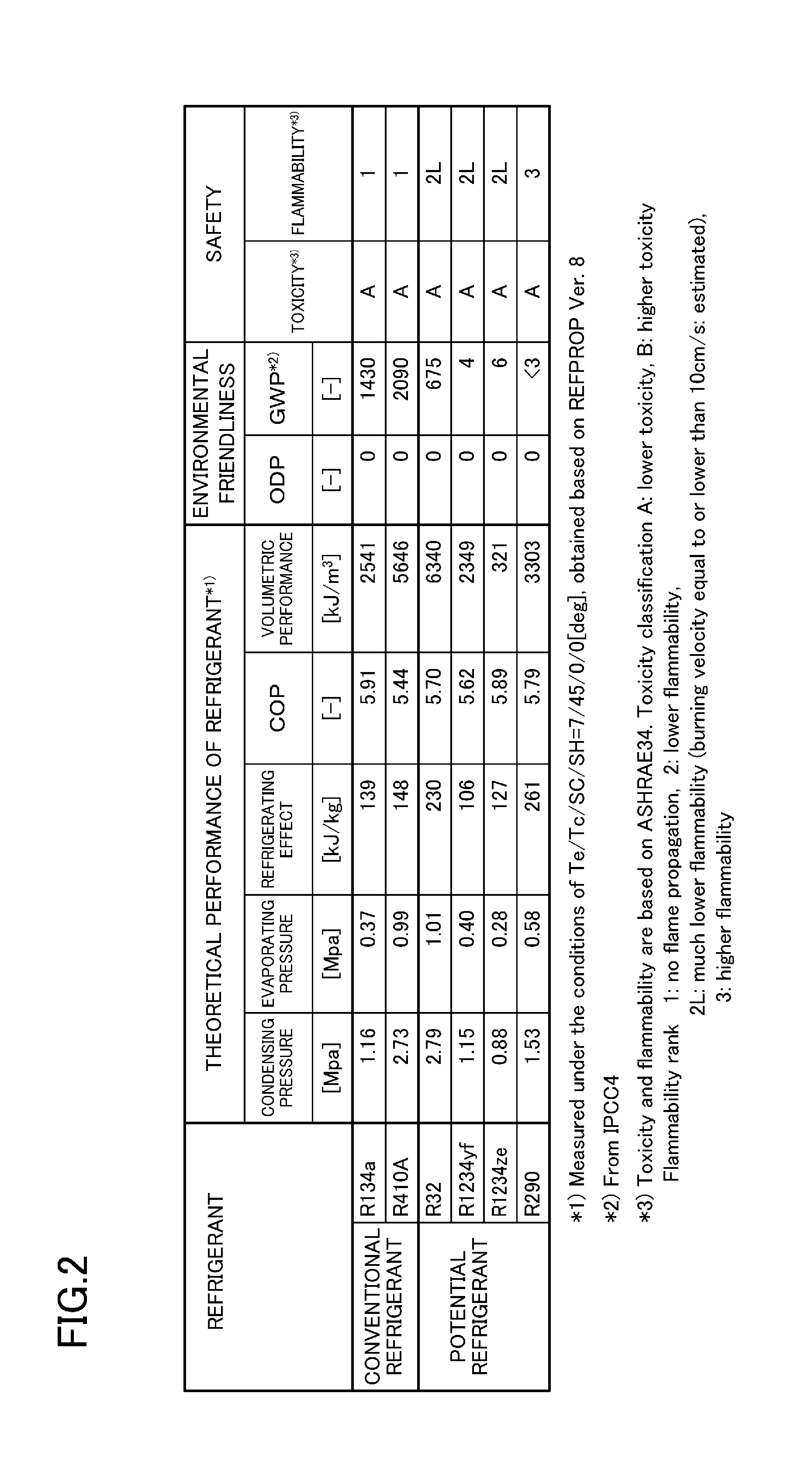
When a refrigerant circuit of an air conditioner, etc. leaks a refrigerant into a room to increase a concentration of the refrigerant in the room, acute toxicity and flammability of the refrigerant may possibly cause accidental intoxication, combustion, suffocation, etc.
In particular, when the refrigerant has a low global warming potential (GWP), which is an index getting attention lately, the refrigerant is more flammable than a refrigerant with a high GWP, and may cause the accidental events with higher possibility.
The above-described measures for safety increase the number and cost of installation processes.
Under these circumstances, the measures for safety are not always taken.

Method used


Image

  • Refrigeration apparatus
  • Refrigeration apparatus
  • Refrigeration apparatus

Examples


first embodiment

Advantages of First Embodiment

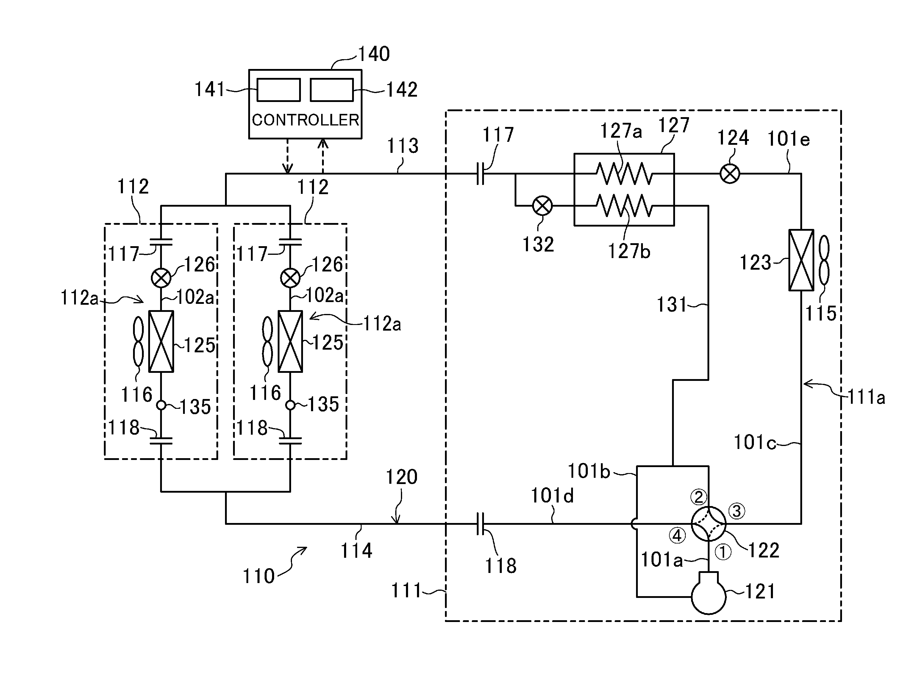
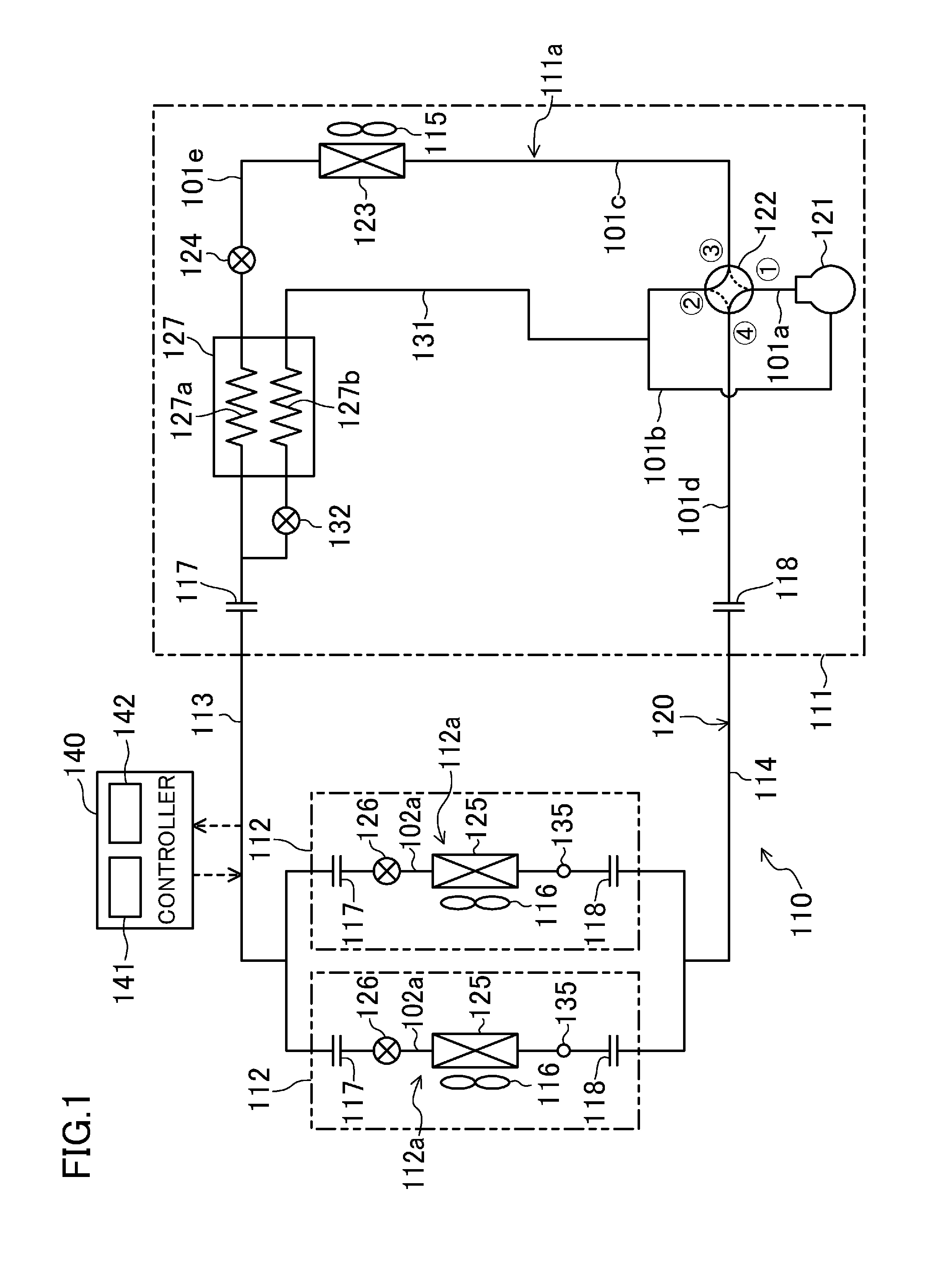
[0081]In the air conditioner (110) of the present embodiment, the refrigeration cycle is performed such that the refrigerant in the indoor circuits (112a) is at the low pressure when the refrigerant has leaked from the indoor circuits (112a). This can reduce the difference between the pressure of the refrigerant in the indoor circuits (112a) and the pressure in the room as much as possible. Thus, the leak rate of the refrigerant can be reduced. As a result, the refrigerant can sufficiently be discharged outside the room by the natural ventilation of the room, thereby reducing the increase in refrigerant concentration in the room. Thus, the refrigerant concentration in the room does not exceed the predetermined limit. The leak of the refrigerant can be reduced at low cost because the valve for cutting the refrigerant flow is no longer necessary.

[0082]According to the present embodiment, the refrigerant in the indoor circuits (112a) is at the low pressure...

second embodiment

[0088]A second embodiment of the present disclosure will be described below. An air conditioner (110) of the present embodiment includes a refrigerant circuit modified from the refrigerant circuit (120) of the first embodiment. Differences between the present embodiment and the first embodiment will be described below.

[0089]In the outdoor circuit (111a) of the present embodiment, an end of the outdoor gas pipe (101d) connected to the fourth port of the four-way switching valve (122) is branched in two, and the two ends are connected to the gas stop valves (118), respectively. In the outdoor circuit (111a), two branch pipes (1010 constitute an end of the outdoor liquid pipe (101e) (i.e., a liquid end of the outdoor circuit (111a). Each of the branch pipes (1010 is connected to the liquid stop valve (117). The outdoor expansion valve (124) is provided in each of the branch pipes (101f).

[0090]In the present embodiment, two liquid communication pipes (113) and two gas communication pipe...

third embodiment

Advantages of Third Embodiment

[0149]In the air conditioner (1) of the present embodiment, the refrigeration cycle is performed such that the refrigerant in the indoor circuits (3a, 4a, 5a) is at the low pressure when the refrigerant has leaked into the room. This can reduce the difference between the pressure of the refrigerant in the indoor circuits (3a, 4a, 5a) and the pressure in the room as much as possible. Thus, the leak rate of the refrigerant can be reduced. As a result, the refrigerant can sufficiently be discharged outside the room by the natural ventilation of the room, thereby reducing the increase in refrigerant concentration in the room. Thus, the refrigerant concentration in the room does not exceed the predetermined limit. The leak of the refrigerant can be reduced at low cost because the valve for cutting the refrigerant flow is no longer necessary.

[0150]In the present embodiment, the cooling operation is performed such that the refrigerant in all the indoor circuit...


PUM


Abstract

An air conditioner includes a refrigerant circuit which connects an outdoor circuit and a plurality of indoor circuits connected in parallel. The air conditioner includes a leak detection section which detects leak of a refrigerant from the indoor circuits, and a control section which circulates the refrigerant to perform a refrigeration cycle when the leak detection section detects leak of the refrigerant such that the refrigerant in the indoor circuits of the refrigerant circuit is at a low pressure. Providing the control section in the air conditioner can reduce the leak of the refrigerant from the indoor circuit at low cost.

Description

TECHNICAL FIELD[0001]The present disclosure relates to a refrigeration apparatus including a refrigeration circuit performing a refrigeration cycle, particularly to measures to prevent leak of a refrigerant from the refrigeration circuit.BACKGROUND ART[0002]When a refrigerant circuit of an air conditioner, etc. leaks a refrigerant into a room to increase a concentration of the refrigerant in the room, acute toxicity and flammability of the refrigerant may possibly cause accidental intoxication, combustion, suffocation, etc. In particular, when the refrigerant has a low global warming potential (GWP), which is an index getting attention lately, the refrigerant is more flammable than a refrigerant with a high GWP, and may cause the accidental events with higher possibility. To avoid the accidental events, IEC 60335-2-40 (particular requirements for electrical heat pumps, air conditioners and dehumidifiers) and the revised draft of ISO5149 (refrigerating systems and heat pumps—safety a...

Claims


Application Information

Patent Timeline
IPC IPC(8): F25B49/00
CPCF25B2500/222F25B49/005F25B13/00F25B49/02F25B2313/0231F25B2313/0233F25B2313/02323F25B2313/02741F25B2313/0291F25B2400/13F25B2500/221F24F11/36
Inventor YAJIMA, RYUZABUROKURIHARA, TOSHIYUKI
Owner DAIKIN IND LTD
Learn More