Radial gap type rotating electrical machine, blower, compressor, and air conditioner

a technology of rotating electrical machines and gap-type gaps, which is applied in the direction of rotating parts of magnetic circuits, magnetic circuit shapes/forms/construction, piston pumps, etc., can solve the problems of high cost of raw materials, rare and expensive elements, and the harsh reality of the requirement of cost reduction of rotating electrical machines, etc., to achieve enhanced demagnetization resistance, reduced torque, and enhanced demagnetization field

Active Publication Date: 2015-08-20
DAIKIN IND LTD
View PDF2 Cites 0 Cited by
  • Summary
  • Abstract
  • Description
  • Claims
  • Application Information

AI Technical Summary

Benefits of technology

[0023]According to the first aspect of the radial gap type rotating electrical machine of the present disclosure, demagnetization field applied to the permanent magnet is reduced when current is applied without lowering field magnetic flux which links with the armature coil from the permanent magnet when no current is applied and thus, a demagnetization resistance is enhanced without lowering torque.
[0024]According to the second aspect of the radial gap type rotating electrical machine of the present disclosure, it becomes easy to control a demagnetization resistance using a length of a region where the magnetic ring becomes locally thin.
[0025]According to the third aspect of the radial gap type rotating electrical machine of the present disclosure, an effect for reducing the demagnetization ratio becomes remarkable by enhancing the magnetic resistance in the thin region.
[0026]According to the fourth aspect of the radial gap type rotating electrical machine of the present disclosure, by providing the recess, it is possible to suppress the reduction in inductive voltage.
[0027]According to a desirable configuration of the fifth aspect of the radial gap type rotating electrical machine of the present disclosure, it is possible to further enhance the magnetic resistance at a position where the recess is provided.
[0028]Objects, features, aspects and merits of the present disclosure will become apparent from the following detailed description and accompanying drawings.

Problems solved by technology

On the other hand, cost of raw materials also increases, and there is an extremely harsh reality of requirement of cost reduction of the rotating electrical machine.
When such a rotating electrical machine is used under various kinds of environments, depending upon temperature characteristics of a permanent magnets, a ferrite magnet has a problem of demagnetization at low temperature, and a neodymium-iron-boron magnet has a problem of demagnetization at high temperature, for example.
However, these elements are rare and expensive.
However, use of a thick permanent magnet leads to cost increase.
Hence, there is a concern that torque ripple while a rotor is driving is increased due to this asymmetric nature.
Hence, reduction in magnetic resistance between adjacent permanent magnets is small, and demagnetization magnetic flux is not effectively reduced.
On the other hand, if the magnetic resistance of the yoke is reduced by reducing its magnetic permeability, torque characteristics and efficiency of the rotating electrical machine are deteriorated.

Method used


Image

  • Radial gap type rotating electrical machine, blower, compressor, and air conditioner
  • Radial gap type rotating electrical machine, blower, compressor, and air conditioner
  • Radial gap type rotating electrical machine, blower, compressor, and air conditioner

Examples


Embodiment Construction

[0041]>

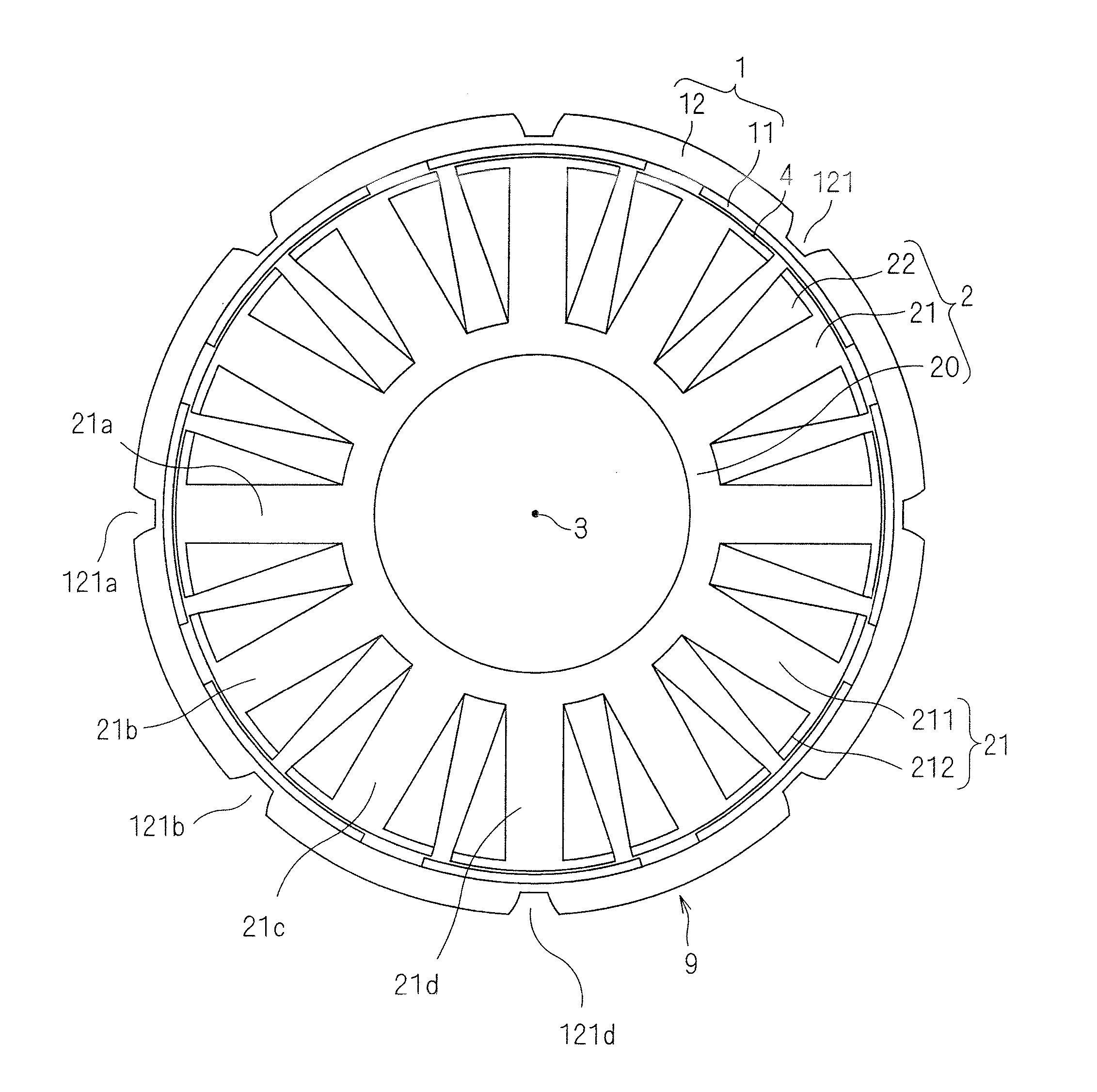
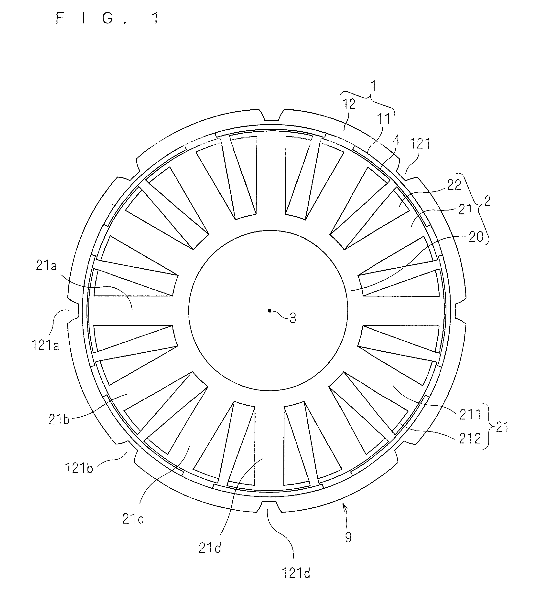
[0042]FIG. 1 is a sectional view showing a configuration of rotating electrical machine 9 according to an embodiment of the present disclosure. FIG. 1 is a sectional view which is perpendicular to a rotation axis 3. The rotating electrical machine 9, including a field 1 which rotates on the rotation axis 3 as a rotation center, and an armature 2 which faces the field 1 through a cylindrical gap 4 in a direction perpendicular to the rotation axis 3, has a radial gap type configuration. Here, a configuration of a so-called outer rotor type radial gap type rotating electrical machine in which the field 1 rotates on an outer periphery side of the armature 2 is exemplified.

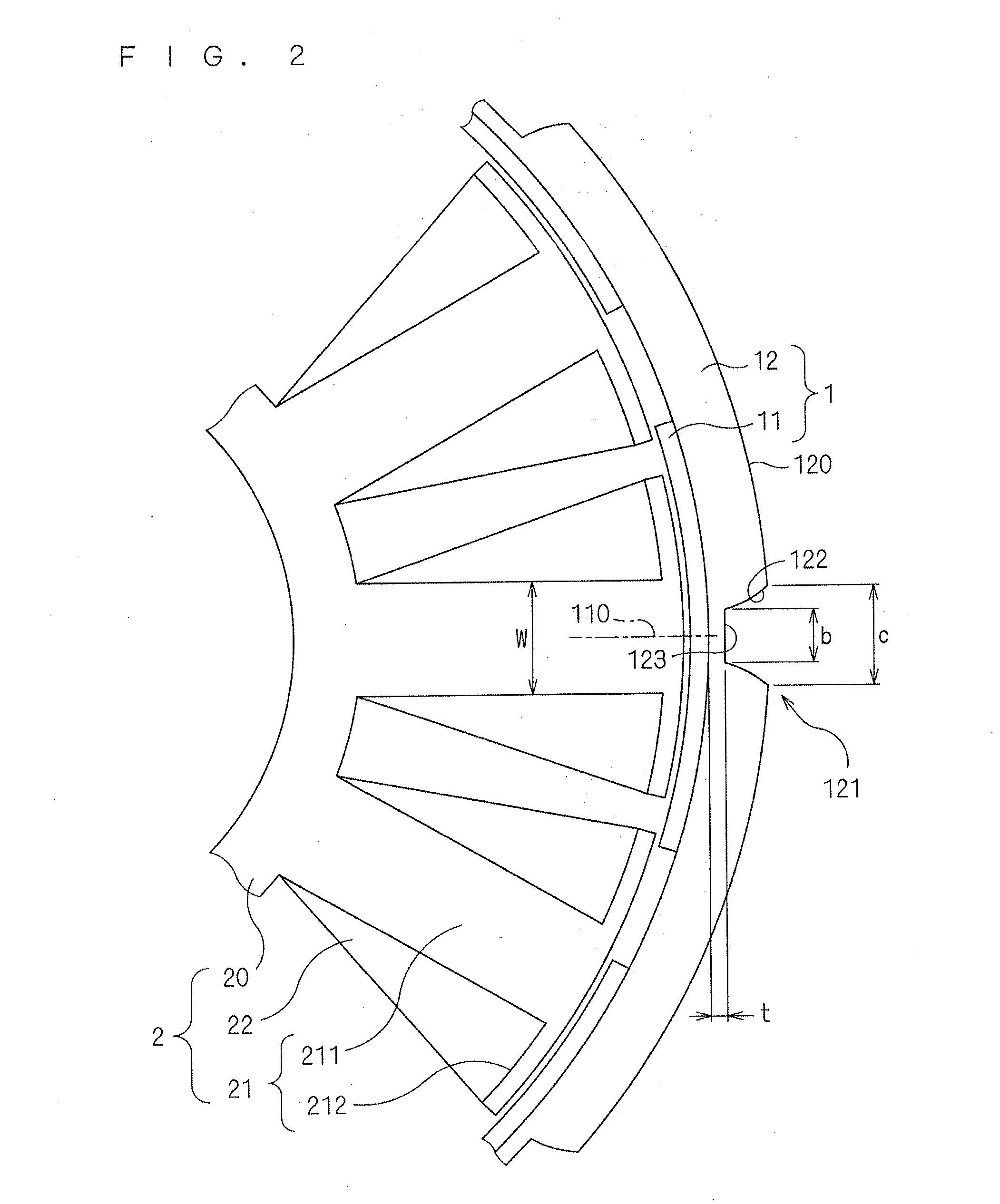
[0043]The field 1 includes permanent magnets 11 for forming a predetermined number of magnetic poles, and the armature 2 faces the permanent magnets 11 through a gap 4. The armature 2 includes teeth 21 and an armature coil 22 which is concentrated-wound around the teeth 21.

[0044]Each of the teeth 21 includes a w...


PUM


Abstract

A radial gap type rotating electrical machine includes a field and an armature. The field includes a permanent magnet and a magnetic ring which serves as a back yoke of the permanent magnet. The magnetic ring is provided at a position farther from the armature than the permanent magnet, and includes a recess at a magnetic pole center. The magnetic pole center is a center of a magnetic pole in a circumferential direction with respect to a rotation axis. A thickness of the recess in the radial direction around the rotation axis as a center comes to locally thin.

Description

TECHNICAL FIELD[0001]The present disclosure relates to a rotating electrical machine, and more particularly, to a so-called radial gap type rotating electrical machine. The rotating electrical machine can be employed as a drive source for a compressor which compresses refrigerant and for a blower in an air conditioner, for example.BACKGROUND ART[0002]A so-called radial gap type rotating electrical machine includes a field which rotates on a rotation axis, and an armature which faces the field through a cylindrical gap in a direction vertical to the rotation axis. The field includes, for example, a permanent magnet and the armature face the permanent magnet through the cylindrical gap. The armature includes teeth and an armature coil which is concentrated-wound around the teeth.[0003]To satisfy both reduction in an environment load such as global warming and realization of convenient and comfortable living environment, requirement of enhancing efficiency with respect to a rotating el...

Claims


Application Information

Patent Timeline
Patent Type & Authority Applications(United States)
IPC IPC(8): H02K1/27F04D13/06F04B17/03H02K1/30
CPCH02K1/2786F04B17/03F04D13/06H02K1/30F04D25/0633F04D25/064H02K21/22H02K2213/03H02K1/2791F04B39/00F04B35/04
Inventor NAKAMASU, SHINASANO, YOSHINARI
Owner DAIKIN IND LTD
Why Eureka
Try Eureka