Method for Operating a Resonant Converter, and Resonant Converter

a resonant converter and resonant technology, applied in the direction of energy industry, efficient power electronics conversion, electric variable regulation, etc., can solve the problems of high switching frequency, high switching loss, and inability to restrict the range of actuation frequency, so as to facilitate zero-voltage no-load switching, reduce complexity of cooling power components, and reduce switching loss

Active Publication Date: 2015-08-20
SIEMENS HEALTHCARE GMBH
View PDF7 Cites 19 Cited by
  • Summary
  • Abstract
  • Description
  • Claims
  • Application Information

AI Technical Summary

Benefits of technology

[0018]The actuation method for selecting the duty factor and actuation frequency facilitates zero-voltage no-load switching. The no-load switching is achieved without complicated snu

Problems solved by technology

As a result, high switching losses (e.g., at relatively high switching frequencies) may occur.
Due to the parasitic capacitances and inductances of the transformer that cause additional points of resonance, it may be impossible to restrict the range of the actuation frequency, similar to sub-resonant actuation.
For example, when an additional range is to be covered for the input and output voltag

Method used


Image

  • Method for Operating a Resonant Converter, and Resonant Converter
  • Method for Operating a Resonant Converter, and Resonant Converter
  • Method for Operating a Resonant Converter, and Resonant Converter

Examples


Embodiment Construction

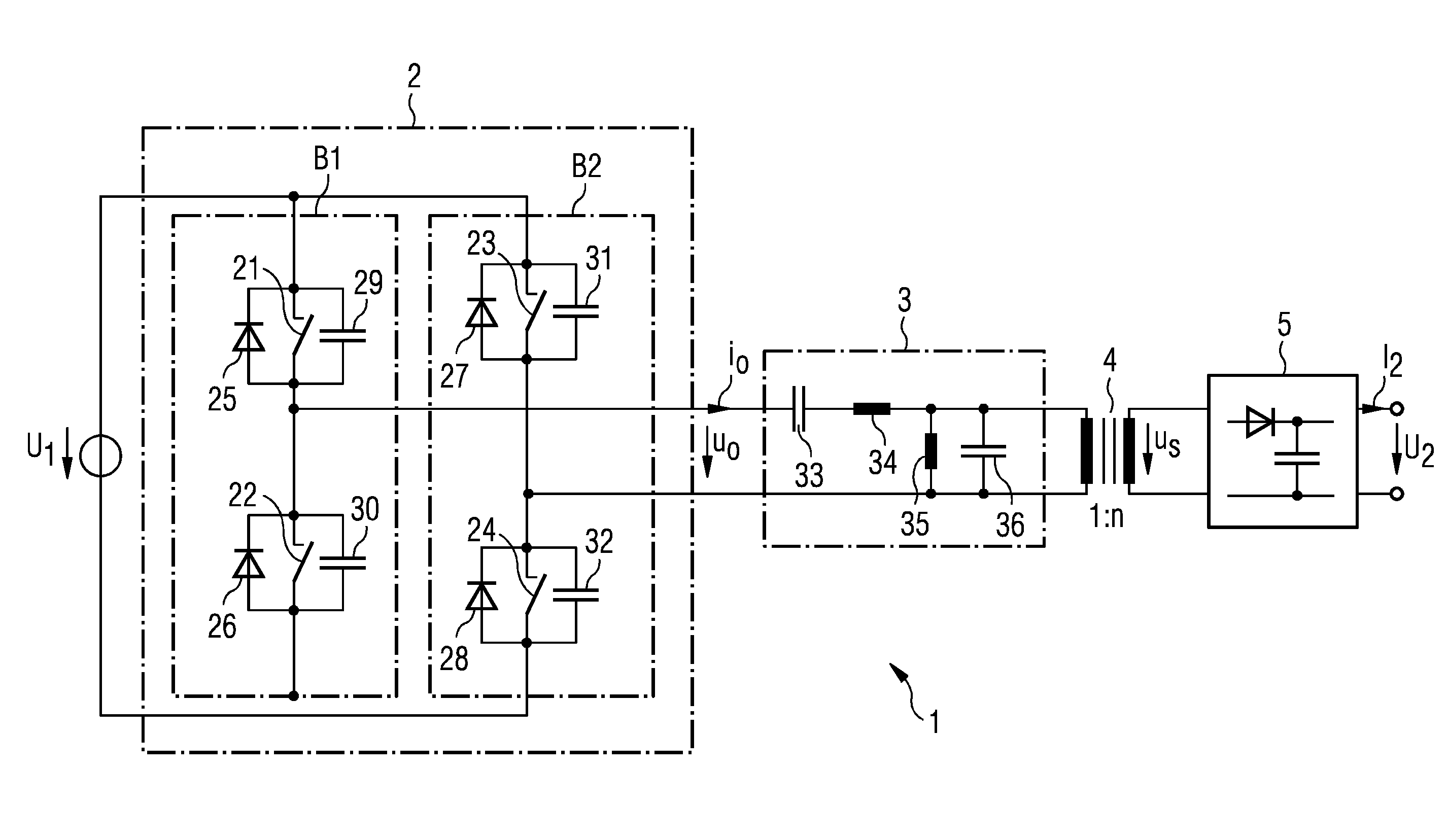
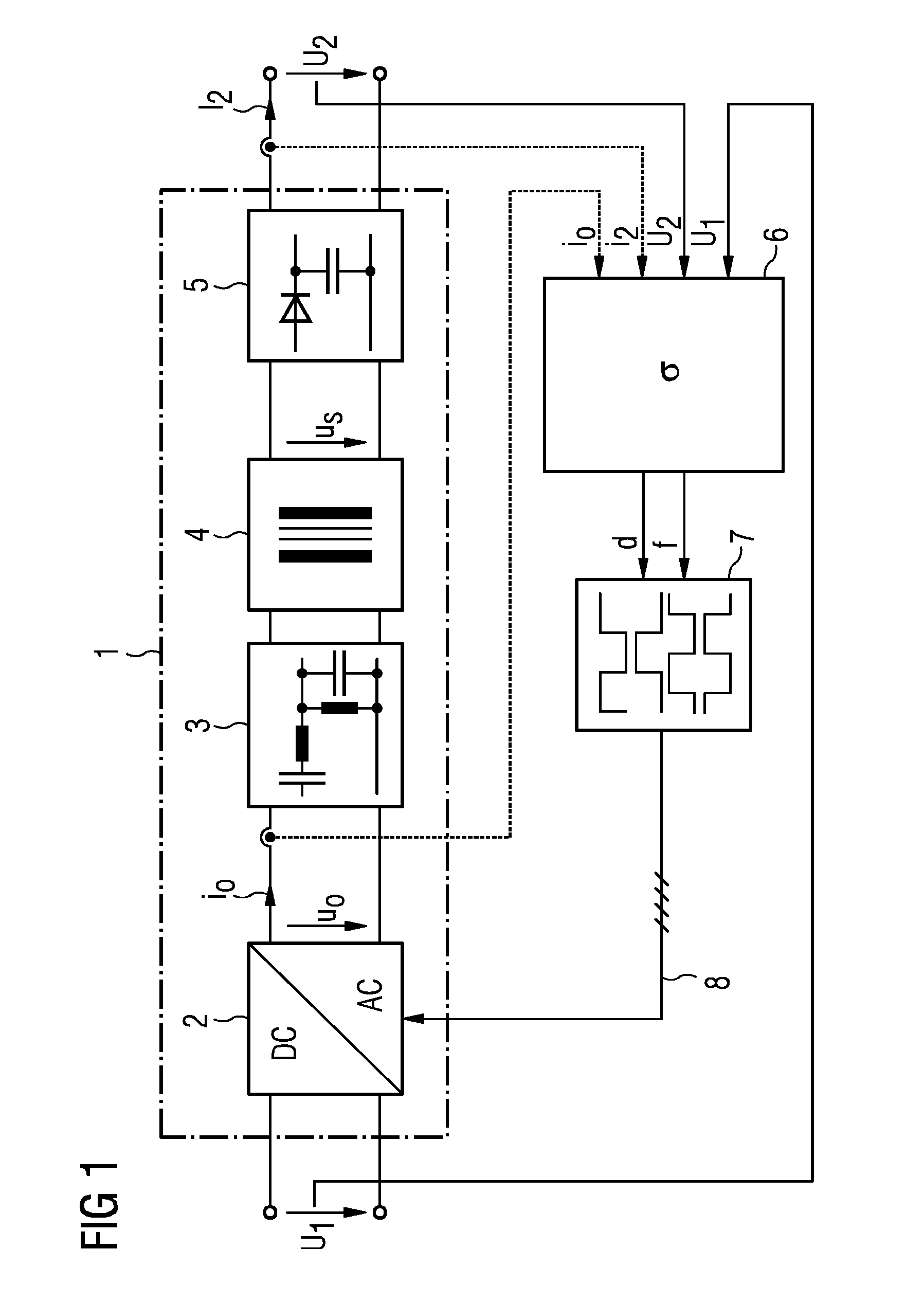
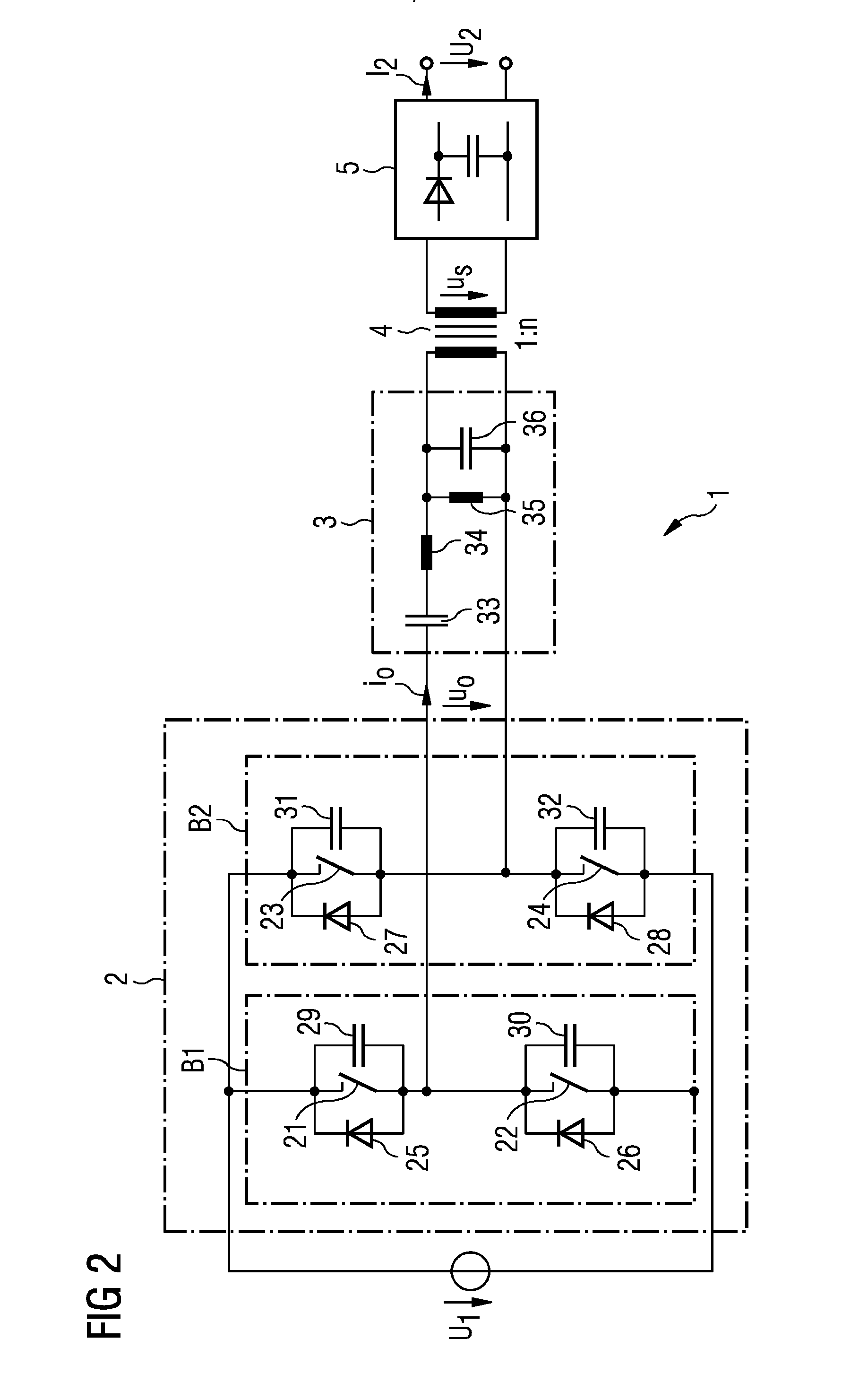
[0031]FIG. 1 shows a block diagram of a circuit arrangement for operation of a resonant converter in accordance with the present teachings. The resonant converter includes a power circuit portion 1 having an inverter circuit 2, a resonant circuit 3, a transformer circuit 4, and a rectifier circuit 5 with smoothing. The resonant converter further includes a regulatory device 6 that actuates a pulse generation circuit 7. The output of the pulse generation circuit 7 provides an actuation signal 8 that switches the switches of the inverter circuit.

[0032]The regulatory device 6 (e.g., a digital regulator) regulates the output voltage U2 and / or the output current I2 using the input voltage U1 by the two manipulated variables, actuation frequency f and duty factor d. The actuation frequency f and duty factor d are used by the pulse generation circuit 7 to produce the actuation signals 8 from the switches of the inverter circuit 2.

[0033]At the output of the inverter circuit 2, the resonant ...


PUM


Abstract

A method for operating a resonant converter having an inverter circuit, the inverter circuit having a plurality of switches, includes: switching each of the switches of the plurality of switches at an actuation frequency and with a phase angle offset relative to one another, such that a voltage of an output of the inverter circuit has a duty factor; and determining the actuation frequency and the duty factor for a prescribable operating point and with a prescribable phase reserve of the resonant converter. A resonant converter and an x-ray generator having a resonant converter are described.

Description

RELATED APPLICATIONS[0001]This application claims the benefit of German Patent Application No. DE 102014202954.6, filed Feb. 18, 2014. The entire contents of the priority document are hereby incorporated herein by reference.TECHNICAL FIELD[0002]The present teachings relate generally to methods for operating soft-switching resonant converters having an inverter circuit and, in some embodiments, to soft-switching resonant converters having an inverter circuit.BACKGROUND[0003]The production of a high voltage for an x-ray tube may use inverter circuits operated at resonance. Such resonant converters are described, for example, in U.S. Patent Application Publication No. 2008 / 0198634 A1.[0004]In a resonant inverter having a series resonant circuit that includes a series capacitor and a series inductor, and half-bridge actuation or full-bridge actuation, the output voltage and the output power may be set by varying the actuation frequency of the semiconductor switches in the bridge paths. ...

Claims


Application Information

Patent Timeline
IPC IPC(8): H02M3/335H01J35/02H02M1/00
CPCH02M3/33515H05G1/10Y02B70/10Y02P80/10H02M1/0064H02M1/0058H02M3/33573H02M3/01H01J35/025H02M3/33507
Inventor WAFFLER, STEFAN
Owner SIEMENS HEALTHCARE GMBH
Why Eureka
Try Eureka