Half-rate clock and data recovery circuit
- Summary
- Abstract
- Description
- Claims
- Application Information
AI Technical Summary
Benefits of technology
Problems solved by technology
Method used
Image

Examples
Embodiment Construction
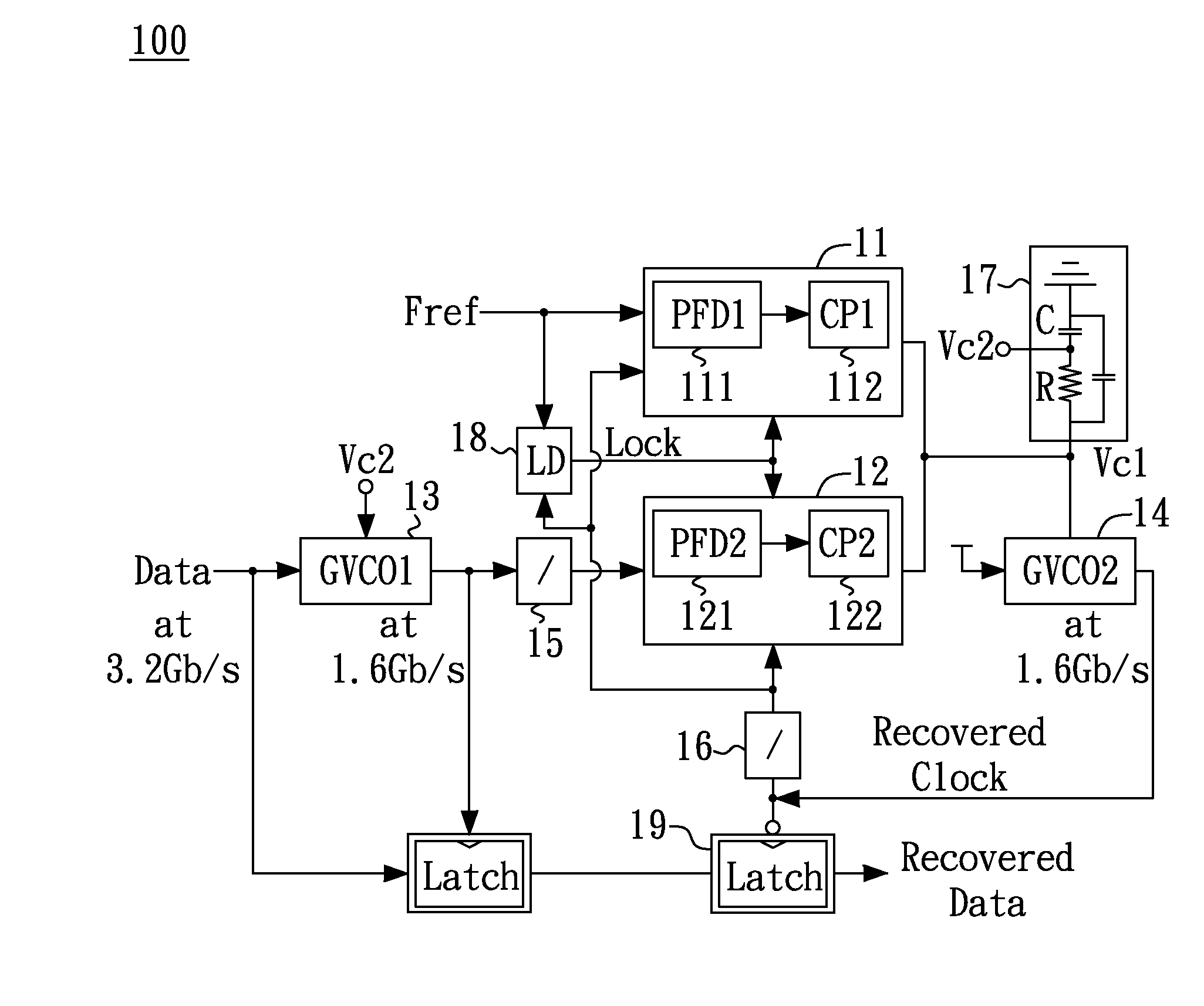
[0013]FIG. 1 shows a block diagram illustrating a half-rate clock and data recovery (CDR) circuit 100 according to one embodiment of the present invention. In the embodiment, the CDR circuit 100 primarily includes a first frequency detector 11, a second frequency detector 12, a first (half-rate) gated voltage-controlled oscillator (GVCO1) 13 and a second (half-rate) gated voltage-controlled oscillator (GVCO2) 14. The first gated voltage-controlled oscillator 13 and the second gated voltage-controlled oscillator 14 generate a first clock and a second clock, respectively. The first gated voltage-controlled oscillator 13 and the second gated voltage-controlled oscillator 14 oscillate at a frequency about half the frequency of an input data, therefore resulting in a half-rate clock and data recovery (CDR) circuit. In one example, an input data rate is 3.2 Gb / s, and the frequency of the first clock and the second clock is 1.6 Gb / s.
[0014]Specifically, the first frequency detector 11 is co...
PUM
 Abstract
Description
Claims
Application Information
 - R&D
- Intellectual Property
- Life Sciences
- Materials
- Tech Scout
- Unparalleled Data Quality
- Higher Quality Content
- 60% Fewer Hallucinations
Browse by: Latest US Patents, China's latest patents, Technical Efficacy Thesaurus, Application Domain, Technology Topic, Popular Technical Reports.
© 2025 PatSnap. All rights reserved.Legal|Privacy policy|Modern Slavery Act Transparency Statement|Sitemap|About US| Contact US: help@patsnap.com