Electronic device and heat dissipation method

a technology of electronic devices and heat dissipation methods, which is applied in the direction of electrical apparatus contruction details, electrical apparatus casings/cabinets/drawers, instruments, etc., can solve the problems of system overheating and insufficient and achieve the effect of reducing the volume of the chamber, increasing the pressure inside the chamber, and improving the heat dissipation efficiency of electronic devices

Active Publication Date: 2015-08-20
ACER INC
View PDF3 Cites 10 Cited by
  • Summary
  • Abstract
  • Description
  • Claims
  • Application Information

AI Technical Summary

Benefits of technology

[0018]Based on above, in the electronic device of the invention, the first opening of the supporting layer and the second opening of the press element are both connected to the chamber of the press element. Accordingly, when the press element is pressed by the user so that the volume of the chamber is decreased, pressure inside the chamber is increased so that air inside the chamber flows to inside the main body of the electronic device through the first opening to form the heat dissipation airflow. In addition, when th...

Problems solved by technology

However, with current trend in compact design for portable electronic devices, some notebook computers are designed to perform heat dissipation merely by using heat dis...

Method used


Image

  • Electronic device and heat dissipation method
  • Electronic device and heat dissipation method
  • Electronic device and heat dissipation method

Examples


Embodiment Construction

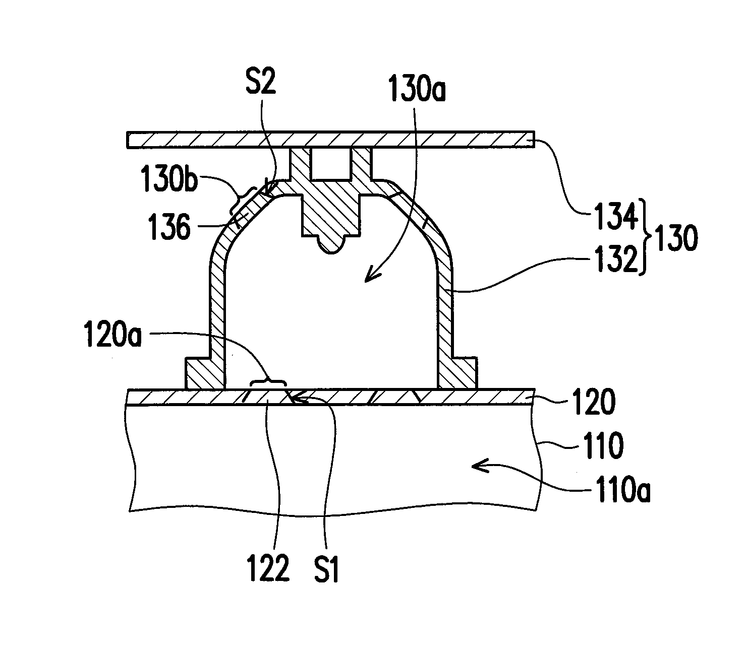
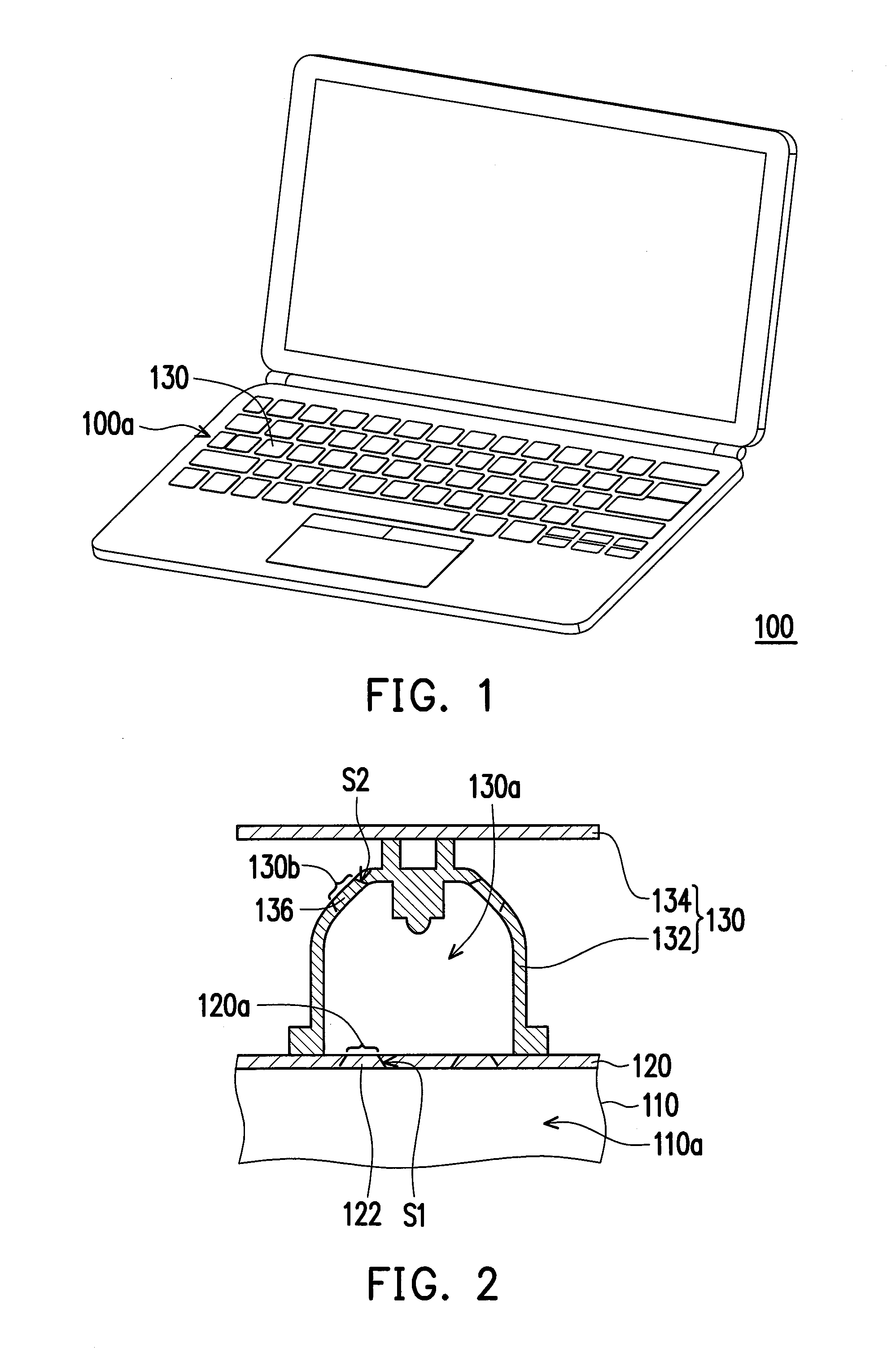
[0026]FIG. 1 is a 3D diagram of an electronic device according to an embodiment of the invention. FIG. 2 is a local cross-sectional diagram of the electronic device of FIG. 1. Referring to FIG. 1 and FIG. 2, an electronic device 100 includes a main body 110, a supporting layer 120 and at least one press element 130 (illustrated in plural in FIG. 1). The main body 110 has an inner space 110a. The supporting layer 120 is disposed on the main body 110 and covers the inner space 110a of the main body 110, wherein the supporting layer 120 has at least one first opening 120a (two of which are illustrated in FIG. 2). The press element 130 is disposed on the supporting layer 120 and has a chamber 130a and at least one second opening 130b (two of which are illustrated in FIG. 2), wherein each first opening 120a and each second opening 130b are connected to the chamber 130a.

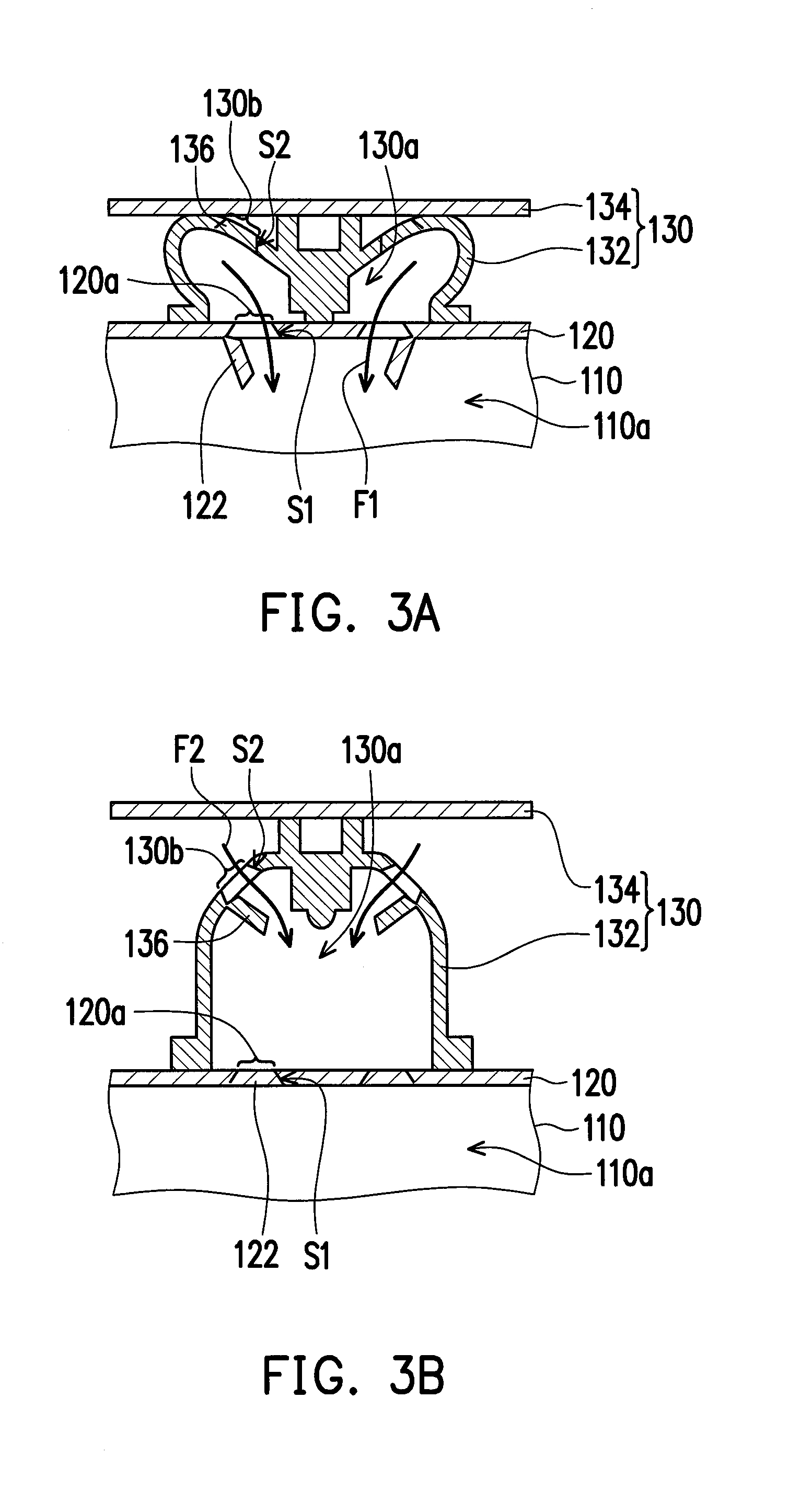
[0027]FIG. 3A is a schematic diagram of the press element of FIG. 1 being pressed. FIG. 3B is a schematic diagram of th...


PUM


Abstract

An electronic device including a main body, a supporting layer and at least one press element is provided. The main body has an inner space. The supporting layer is disposed on the main body and covers the inner space, wherein the supporting layer has at least one first opening The press element is disposed on the supporting layer and has a chamber and at least one second opening, wherein the first opening and the second opening are connected to the chamber. When the press element is pressed and elastically deformed, air inside the chamber flows to the inner space through the first opening. When the press element is stopped being pressed and restored, air outside the chamber flows to inside the chamber through the second opening. In addition, a heat dissipation method adapted to the electronic device is also provided.

Description

CROSS-REFERENCE TO RELATED APPLICATION[0001]This application claims the priority benefit of Taiwan application serial no. 103105527, filed on Feb. 19, 2014. The entirety of the above-mentioned patent application is hereby incorporated by reference herein and made a part of this specification.BACKGROUND OF THE INVENTION[0002]1. Field of the Invention[0003]The invention relates to an electronic device and a heat dissipation method, and more particularly, to an electronic device having a press element and a heat dissipation method thereof.[0004]2. Description of Related Art[0005]Notebook computer generally include functions similar to that of desktop computer and designs in reducing volume and weight so that a user may carry it around with ease, which makes the notebook computer a portable tool indispensable for specific users. With continuous price drop of notebook computer, the specific users even directly use the notebook computer as a replacement of the desktop computer.[0006]Heat ...

Claims


Application Information

Patent Timeline
IPC IPC(8): H05K7/20G06F1/20
CPCG06F1/203H05K7/20145G06F1/1662H01H9/52H01H13/82H01H2213/002H01H2213/008H01H2227/02H01H2231/042
Inventor LIU, CHE-JUNG
Owner ACER INC
Why Eureka
Try Eureka