

Grinding-supporting device
- Summary
- Abstract
- Description
- Claims
- Application Information
AI Technical Summary
Benefits of technology
Problems solved by technology
Method used
Image

Examples
Embodiment Construction
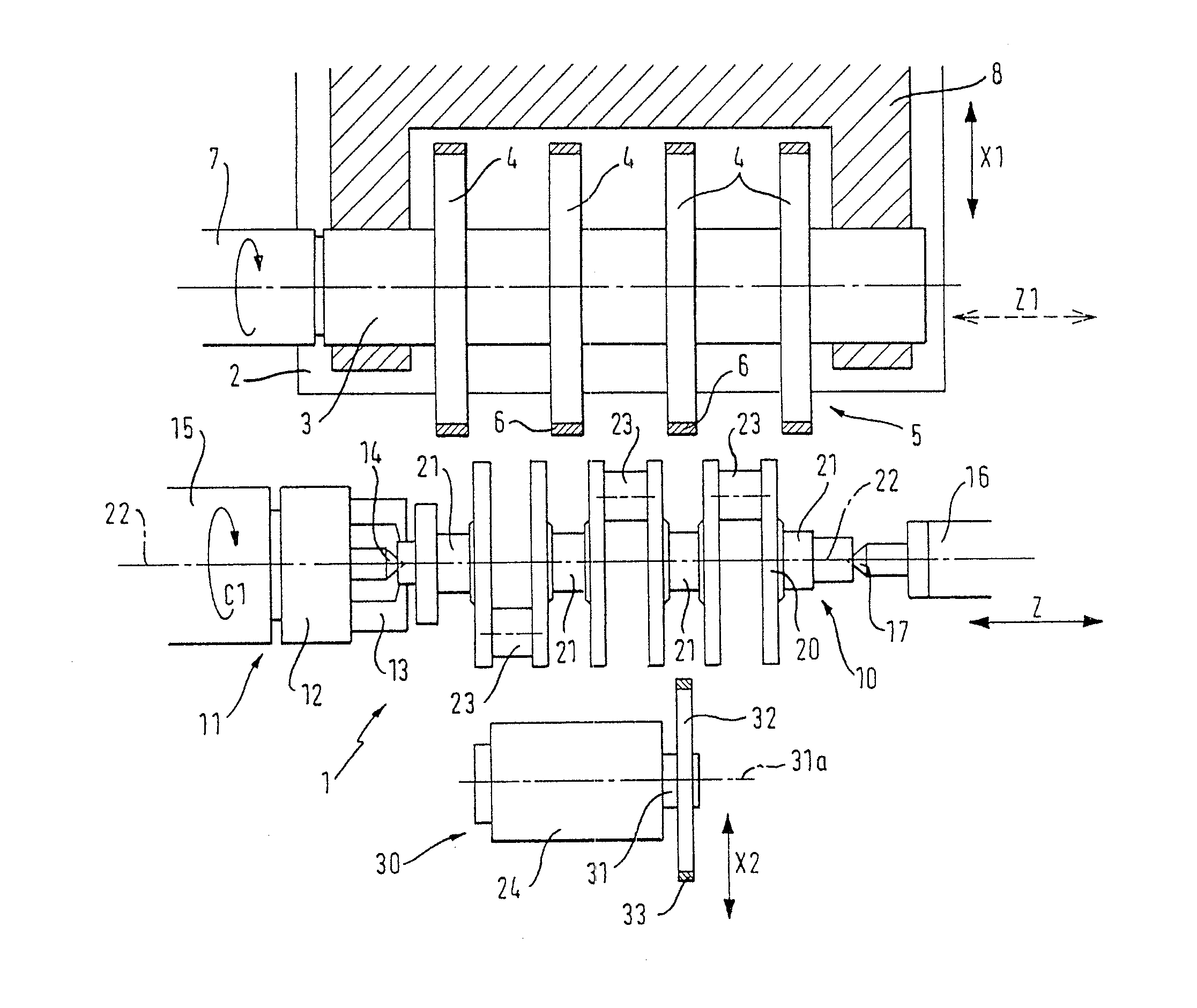
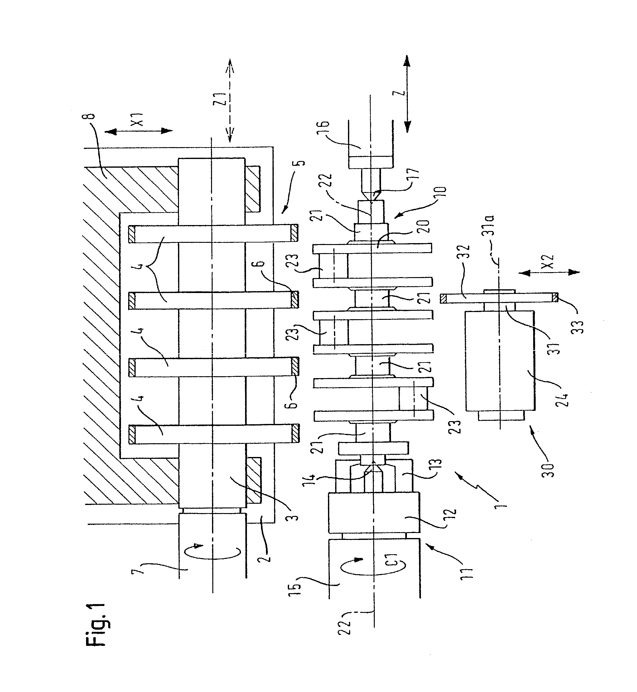
[0036]FIG. 1 shows a partial plan view of a grinding machine 1 according to the invention. Located in the rear region on an infeed slide 2 is a rotationally driven grinding spindle 3 which accommodates a plurality of grinding wheels 4 for grinding centrally clamped bearing points 21 of the workpiece 10. The grinding wheels 4 form the grinding wheel set 5 and have a grinding layer 6 on their circumference. They are set in rotation via the grinding spindle 3 and the rotary drive 7 thereof, which is indicated by the curved arrow. Here, the multiple-bearing grinding headstock 8 is fitted with four grinding wheels 4 for the simultaneous grinding of the four main bearings 21 of a crankshaft 20 and can be fed in and removed in the direction of the double arrow X1, i.e. at right angles to the center axis of the workpiece 10.
[0037]Here, the workpiece 10 is a crankshaft 20, the central main bearings 21 of which establish the center axis of the workpiece 10 and thus the rotation axis 22 thereo...
PUM
| Property | Measurement | Unit |
|---|---|---|
| Angle | aaaaa | aaaaa |
| Friction | aaaaa | aaaaa |
Abstract
Description
Claims
Application Information