All-suture suture anchor systems and methods
a suture and anchoring technology, applied in the field of soft tissue to bone repair procedures, can solve the problems of unable to repair, prone to pull out, and likely to be pulled toward the surface of the bone,
- Summary
- Abstract
- Description
- Claims
- Application Information
AI Technical Summary
Benefits of technology
Problems solved by technology
Method used
Image
Examples
first embodiment
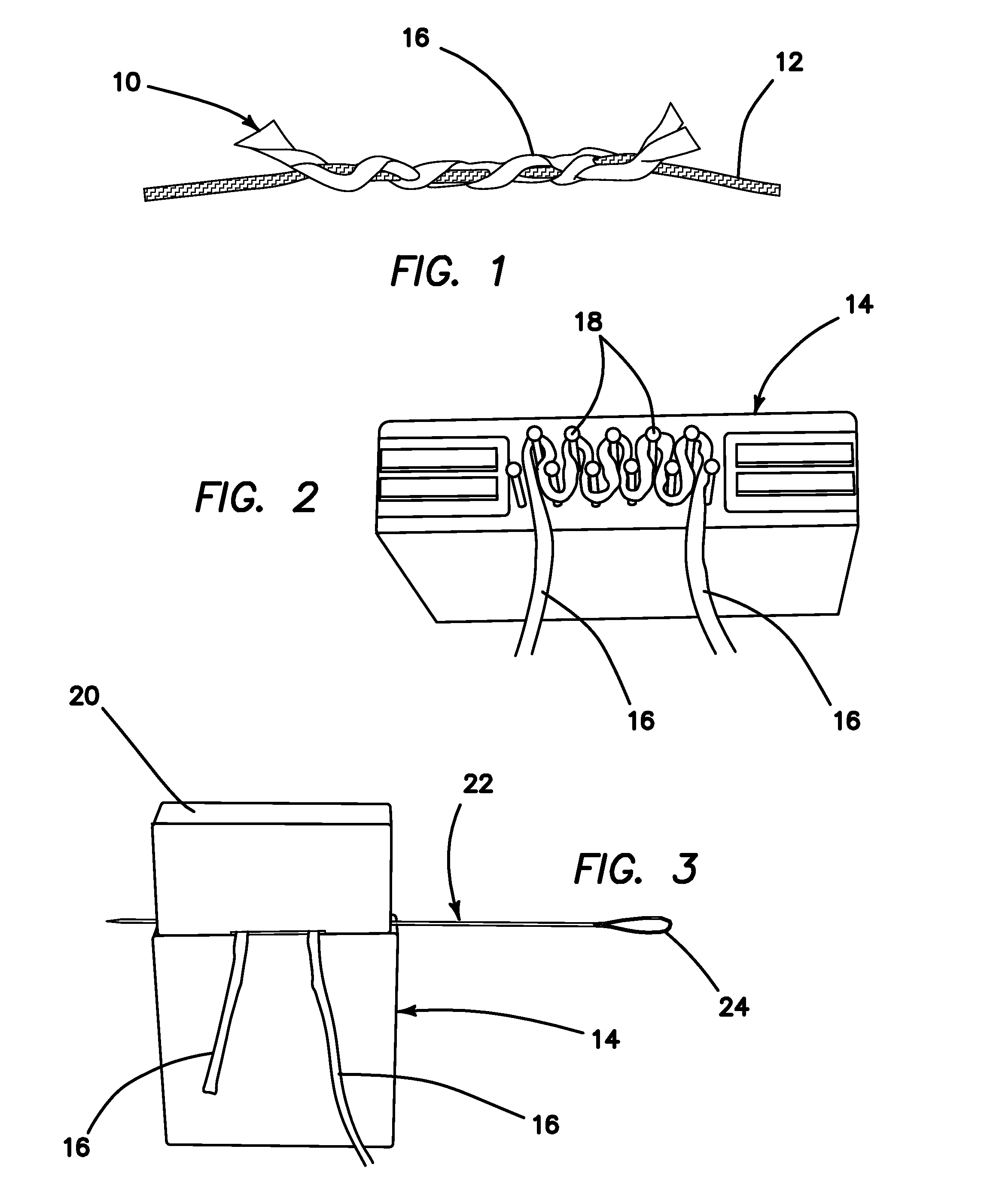
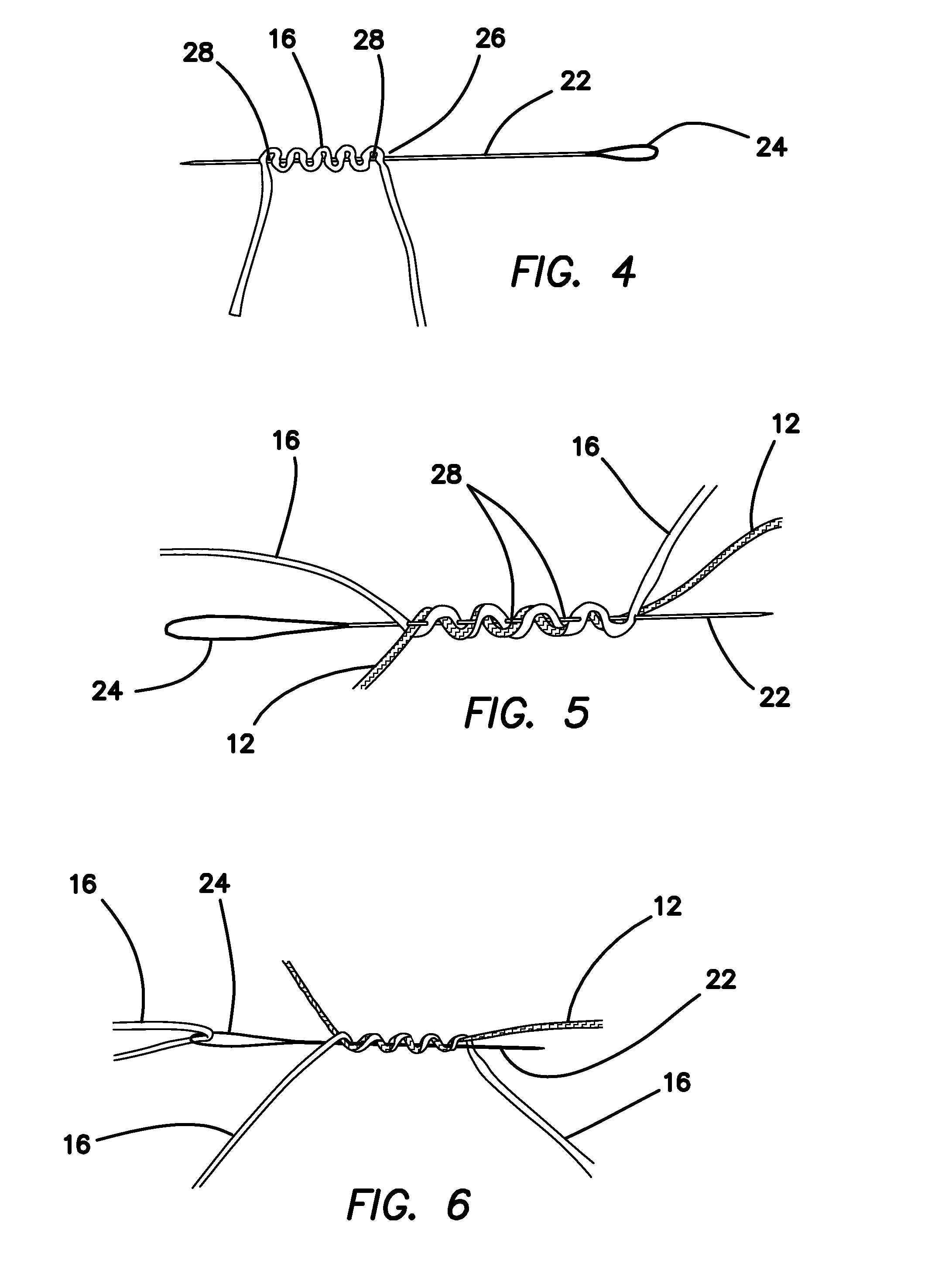
[0038]Thus, FIG. 1 illustrates a suture anchor 10 constructed in accordance with the principles of the present invention. This embodiment is a single-loaded anchor. FIG. 2 illustrates an assembly fixture 14, wherein a piece of size 2 suture 16 (anchor suture) is wrapped around pins 18 of the fixture 14, as shown. As shown in FIG. 3, a cap 20 is placed on the fixture 14 and a needle 22 with a snare loop 24 on one end is pierced through the anchor suture 16. Then, the assembly 26 is removed from the fixture, as shown in FIG. 4.
[0039]Referring to FIG. 5, one free end of the floating suture 12 is passed back and forth through loops 28 formed between the suture 16 and the needle 22 in the previous step. As shown in FIGS. 6 and 7, one end of the anchor suture 16 is placed in the snare loop 24 and pulled back through the suture strand.
[0040]FIG. 8 illustrates a step wherein the floating suture 12 has been pulled tight, and the ends of the anchor suture have been cut off to complete the anc...
second embodiment
[0041]Now with reference to FIG. 9, a suture anchor 10 constructed in accordance with the present invention is illustrated. This embodiment is a double-loaded anchor. This embodiment 10 is constructed as shown in FIGS. 10-18. FIG. 10 illustrates a first step in the method of constructing the double-loaded anchor 10 of FIG. 9, wherein a needle 22 with a snare loop 24 on the end is passed through the core of a size 2 piece of suture 16 (anchor suture). The step is repeated with a second needle 30 having a snare loop 32 being passed through a second piece of suture 16, as shown. In FIG. 11, the long end of second anchor suture 16 is placed into the snare loop 24. The needle 22 is pulled to pull the suture end through the core of the second anchor suture 16. FIG. 12 illustrates the result of this step. Then, the long end of the first anchor suture 16 is placed in the snare loop 32 and pulled through the core of the second anchor suture 16. FIG. 13 illustrates the resulting anchor loop 3...
embodiment 10
[0057]Another alternative suture anchor embodiment 10 is illustrated in FIGS. 24-27. This anchor is constructed by wrapping anchor suture around a pin and tying two alternative half-hitches 62 (FIG. 25). The two limbs are then wrapped around another pin, and more half-hitches 62 are tied. The center loop 64 is wrapped around a larger pin to allow for easier loading onto the inserter inner shaft 38. The floating suture or sutures are then passed through the loops 66 (created by the pins) to complete the construct.
[0058]This anchor is constructed by forming a double loop of suture, then wrapping one of the free ends around the loop approximately twenty times. The loop is then tightened around two posts a distance apart by pulling both free ends. This creates a loop, similar to the anchor loop of the previous double-loaded anchor embodiment 10 of FIGS. 10-18. The remaining construction steps are the same as previously described—the anchor is wrapped around a snare with alternating twis...
PUM
 Abstract
Description
Claims
Application Information
 - R&D
- Intellectual Property
- Life Sciences
- Materials
- Tech Scout
- Unparalleled Data Quality
- Higher Quality Content
- 60% Fewer Hallucinations
Browse by: Latest US Patents, China's latest patents, Technical Efficacy Thesaurus, Application Domain, Technology Topic, Popular Technical Reports.
© 2025 PatSnap. All rights reserved.Legal|Privacy policy|Modern Slavery Act Transparency Statement|Sitemap|About US| Contact US: help@patsnap.com


