Optical device with diffractive grating

a technology of optical devices and diffractive gratings, applied in the field of optical devices, can solve the problems of inability to achieve the desired effect, inability to transmit diffraction orders, and inability to achieve transmission, etc., to achieve the effect of optimizing the suppression of the rainbow

Active Publication Date: 2015-09-10
DISPELIX OY
View PDF6 Cites 28 Cited by
  • Summary
  • Abstract
  • Description
  • Claims
  • Application Information

AI Technical Summary

Benefits of technology

[0021]According to one embodiment, the first and second grating layers are of equal thickness. This provides maximal suppression of non-zero transmitted diffraction orders and therefore rainbow effect, at least when the internal structures (dimensions and refractive indices) of the grating layers are similar.
[0022]Alternatively, the first and second grating layers are non-identical in their material properties and have different thicknesses. This is beneficial if the selection of usable materials is limited and the grating layers cannot be made identical. The thicknesses can be still used to optimize the suppression of the rainbow effect.
[0023]According to one embodiment, the zones of the first grating layer having higher refractive index are fully aligned with the zones of the second grating layer having lower refractive index and vice versa. In particular, the second grating layer may have a similar internal structure as the first grating layer but being laterally shifted by half of the grating period in the periodic direction of the grating to provide perfect alignment.

Problems solved by technology

At least some of the abovementioned solutions, however, suffer from an undesired effect caused by transmitted light coming through the diffracting gratings to the observer's eye, i.e. the so-called rainbow effect.
This may make the diffractive combiner element technology practically useless in some applications, unless the problem is solved.
Transmitted diffraction orders are, however still considerably strong, whereby the result is far from optimal regarding the rainbow interference image.
In addition, the structure is relatively difficult to manufacture.

Method used


Image

  • Optical device with diffractive grating
  • Optical device with diffractive grating
  • Optical device with diffractive grating

Examples


Embodiment Construction

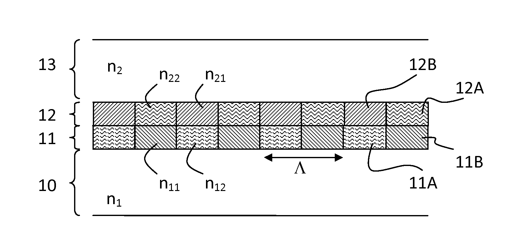
[0048]FIG. 1 illustrates a general structure of the two-layer grating according to the invention. The grating comprises a first grating layer 11 and a second grating layer 12. The both grating layers have the same grating period (Λ) and are binary. The first grating layer is composed of a periodic pattern of alternating material zones 11A and 11B having different refractive indices n11 and n12, respectively. Likewise, the second grating layer is composed of a periodic pattern of alternating material zones 12A and 12B having different refractive indices n21 and n22, respectively. On the first side of the two-layer grating there is provided a first optically transparent material layer 10 having a refractive index n1 and on the second side of the grating there is provided a second optically transparent material layer 13 having a refractive index n2. The layers 10, 13 on one or both sides of the grating may comprise also air (or vacuum) layers, i.e. lack any solid material.

[0049]A simpl...


PUM


Abstract

The invention relates to optical devices comprising a transparent substrate and a first transparent grating layer on the substrate, the grating layer comprising periodically alternating zones having different refractive indices. According to the invention, the device comprises a second transparent grating layer located on top of the first grating layer and also comprising periodically alternating zones having different refractive indices so that the zones of the first grating layer having higher refractive index are at least partly aligned with the zones of the second grating layer having lower refractive index and vice versa, the second grating layer reducing the amount of light diffracted to non-zero transmission orders. The invention allows for reducing the so-called rainbow effect for example in head-up displays (HUDs).

Description

FIELD OF THE INVENTION [0001]The invention relates to optical devices. In particular, the invention relates to out-coupling gratings which can be used in head-up displays (HUDs), near-to-eye displays (NEDs), or exit pupil expanders (EPEs), for example. The present device comprises a light-guiding substrate and a grating arranged within the substrate or on at least portion of a surface of the substrate.BACKGROUND OF THE INVENTION[0002]HUDs and NEDs comprise tree fundamental parts: a light projector, a computing unit controlling the projector, and an optical combiner which is adapted to show the light from the projector to a see-through display allowing the user of the HUD or NED to see both the scenery behind the display and the projected light without requiring the user to look away from his usual viewpoint. The optical combiner may be based on diffractive optical elements, sometimes referred to as holographic optical elements (HOEs).[0003]WO 2006 / 064301 discusses near-to-eye displa...

Claims


Application Information

Patent Timeline
Patent Type & Authority Applications(United States)
IPC IPC(8): G02B27/01G02B27/42
CPCG02B27/0101G02B27/4211G02B2027/0112G02B27/4288G02B27/4272G02B5/1809G02B5/1823G02B6/0016G02B6/0026G02B27/0172G02B5/1819G02B6/00G02B27/18G02B27/44G02F1/0102G02F1/292G09F9/00G09F19/18H04N9/31G02B6/0035
Inventor SUNNARI, ANTTIHUTTUNEN, OLLI-HEIKKIOLKKONEN, JUUSO
Owner DISPELIX OY
Why Eureka
Try Eureka