Image processing device, imaging system, and image processing program

a technology of image processing and imaging system, applied in image enhancement, instruments, applications, etc., to achieve the effect of reducing the influence of lung field motion

Inactive Publication Date: 2015-09-10
KONICA MINOLTA INC
View PDF1 Cites 9 Cited by
  • Summary
  • Abstract
  • Description
  • Claims
  • Application Information

AI Technical Summary

Benefits of technology

[0009]The present invention has been made to solve the above problem. An object of the present invention is to reduce the influence of lung field motion on processing of medical video images, and appropriately process medical video images, regardless of lung field motion.

Problems solved by technology

This problem is also caused in a case where processing other than difference image generation is performed, or where a medical video image is generated by an imaging technology other than radiography, for example.

Method used


Image

  • Image processing device, imaging system, and image processing program
  • Image processing device, imaging system, and image processing program
  • Image processing device, imaging system, and image processing program

Examples


first embodiment

(1) First Embodiment

(1.1) Imaging System

[0032]A first embodiment relates to an imaging system.

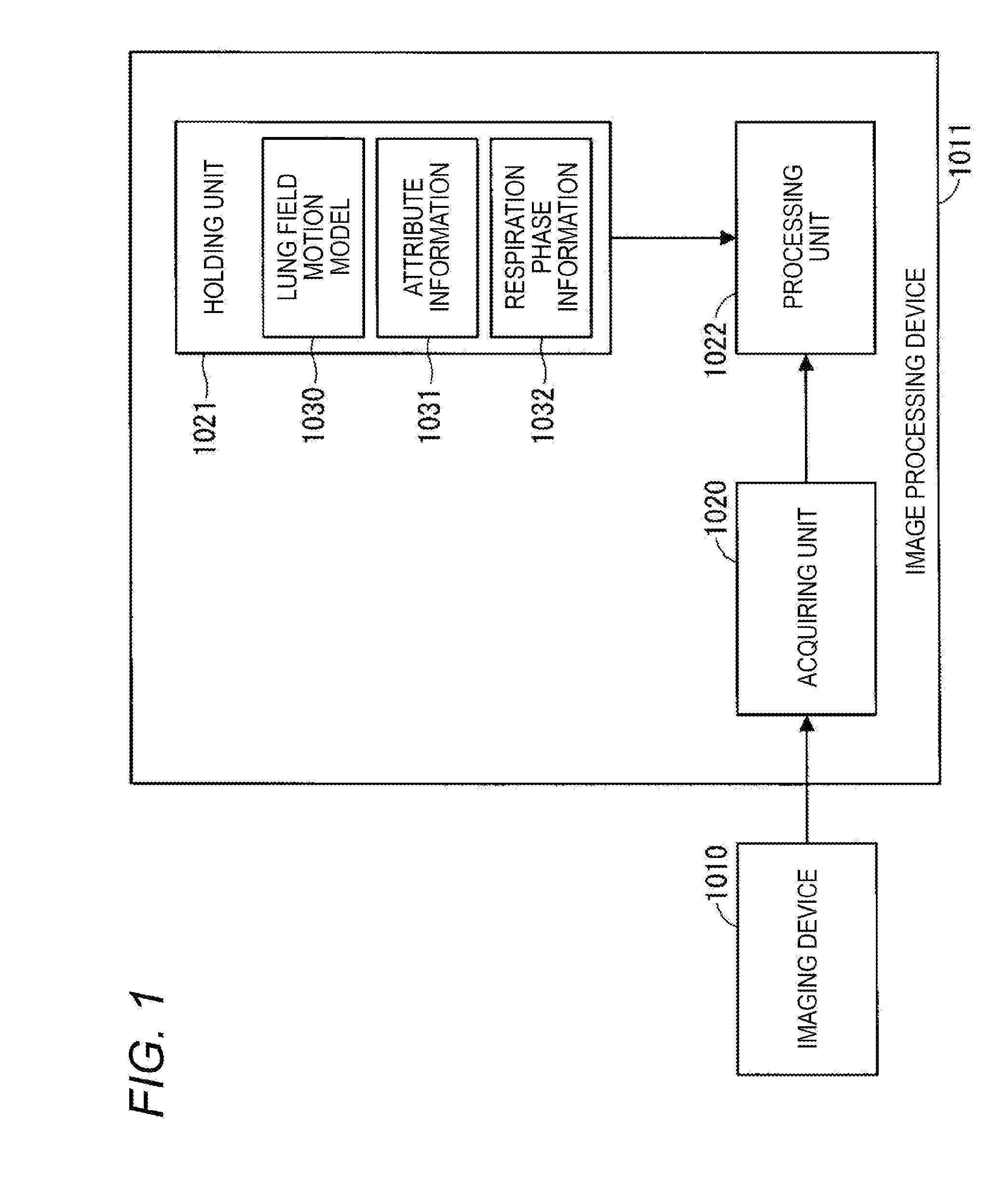
[0033]The block diagram in FIG. 1 shows an imaging system of the first embodiment.

[0034]The imaging system 1000 shown in FIG. 1 includes an imaging device 1010 and an image processing device 1011.

[0035]The imaging device 1010 generates medical video images by radiography. The imaging device 1010 generates X-rays from an X-ray tube, causes the generated X-rays to penetrate through a human body, and detects the X-rays having penetrated through the human body with a flat panel detector (FPD). With this, the imaging device 1010 images structures in the human body, and generates a frame image showing the structures in the human body. The imaging device 1010 performs imaging twice or more, and generates a medical video image including two or more frame images. A medical video image is a two-dimensional image, and is digital data. Alternatively, the imaging device 1010 may generate a medical video...

second embodiment

(2) Second Embodiment

[0076]A second embodiment relates to a processing unit that replaces the processing unit of the first embodiment.

[0077]The block diagram in FIG. 12 shows the processing unit of the second embodiment. The schematic view in FIG. 13 shows an example of processing to be performed by the processing unit of the second embodiment. FIG. 14 is a schematic view of example deformation of a frame image. The example processing shown in FIG. 13 is to be performed in a case where lung field motion models representing lung field motion differences due to positions in the vertical direction are prepared for respective attributes. The prepared lung field motion models may differ from those shown in FIG. 13.

[0078]The processing unit 2000 shown in FIG. 12 includes a selecting unit 2010, an adjusting unit 2011, a deforming unit 2012, and a process executing unit 2013.

[0079]The selecting unit 2010 identifies the attribute of a medical video image, and selects the lung field motion mo...

third embodiment

(3) Third Embodiment

[0085]A third embodiment relates to a processing unit that replaces the processing unit of the first embodiment.

[0086]The block diagram in FIG. 15 shows the processing unit of the third embodiment. The schematic view in FIG. 16 shows an example of processing to be performed by the processing unit of the third embodiment. The example processing shown in FIG. 16 is to be performed in a case where lung field motion models representing lung field motion differences due to positions in the vertical direction are prepared for respective attributes.

[0087]The processing unit 3000 shown in FIG. 15 includes a selecting unit 3010, an adjusting unit 3011, a searching unit 3012, and a process executing unit 3013.

[0088]The selecting unit 3010 identifies the attribute of a medical video image, and selects the lung field motion model 3030 corresponding to the identified attribute from between two or more lung field motion model 1030 by referring to attribute information 1031, as...


PUM


Abstract

An image processing device includes an acquiring unit configured to acquire a medical video image obtained by imaging of lungs, a holding unit configured to hold a lung field motion model, the lung field motion model simulating lung field motion, and a processing unit configured to process the medical video image by using the lung field motion model.

Description

[0001]The entire disclosure of Japanese Patent Application No. 2014-045084 filed on Mar. 7, 2014 including description, claims, drawings, and abstract are incorporated herein by reference in its entirety.BACKGROUND OF THE INVENTION[0002]1. Field of the Invention[0003]The present invention relates to processing of medical video images.[0004]2. Description of the Related Art[0005]In imaging of a chest X-ray video image, X-rays are generated from an X-ray tube, the generated X-rays are caused to pass through a human body, and the X-rays having passed through the human body are detected by a flat panel detector (FPD), for example. A chest X-ray video image is generated to aid a medical doctor in diagnosing a patient, for example.[0006]US 2012 / 0300904 A discloses a technology for processing chest X-ray video images. In the technology disclosed in the above publication, a difference value between the pixels located in the same positions in one frame image and another frame image is determ...

Claims


Application Information

Patent Timeline
Patent Type & Authority Applications(United States)
IPC IPC(8): G06T7/00A61B6/00G06T7/20A61B5/08
CPCG06T7/0012A61B5/08A61B6/5205G06T2207/30061G06T7/20G06T2207/10016A61B6/5217A61B6/486A61B6/5264G06T5/003G06T7/0016G06T2207/10081G06T2207/10088G06T2207/10116G06T2207/10132G06T7/251G06T7/254
Inventor FUJIWARA, KOICHITOYAMA, OSAMUYAMATO, HIROSHISHIMAMURA, KENTA
Owner KONICA MINOLTA INC
Why Eureka
Try Eureka