Position-Dependent Hybrid Domain Packet Loss Concealment

a hybrid domain and packet loss technology, applied in the field of audio signal processing, can solve the problems of reducing the perceived speech quality of the receiver side, affecting the quality of the audio, and affecting the loss position, and achieve the effect of increasing the loss position

Active Publication Date: 2015-09-10
DOLBY LAB LICENSING CORP
View PDF4 Cites 33 Cited by
  • Summary
  • Abstract
  • Description
  • Claims
  • Application Information

AI Technical Summary

Benefits of technology

[0026]The method may further comprise applying a long-term attenuation to the estimate of the current frame, wherein the long-term attenuation depends on the loss position. Typically, the long-term attenuation increases with increasing loss position. As such, the long-term attenuation may provide for a fade-out of the estimates of frames (corresponding to lost packets) across a plurality of lost packets, thereby providing a smooth transition from concealment to silence (if the number of lost packets exceeds a maximum allowed number of lost packets).

Problems solved by technology

Packet loss occurs frequently in VoIP or wireless voice communication systems.
Lost packets result in clicks or pops or other artifacts that greatly degrade the perceived speech quality at the receiver side.
However, these approaches degrade audio quality notably in the event of consecutive packet loss, often generating artifacts due to the repetition of similar content over several frames or due to low signal periodicity.
PLC in the time domain typically cannot be directly applied to decoded speech which has been determined from a transform domain codec due to an extra aliasing buffer.
However, such schemes may cause “robotic” sounding artifacts and may lead to rapid quality degradation, notably if PLC is used for a plurality of lost packets.

Method used


Image

  • Position-Dependent Hybrid Domain Packet Loss Concealment
  • Position-Dependent Hybrid Domain Packet Loss Concealment
  • Position-Dependent Hybrid Domain Packet Loss Concealment

Examples


Embodiment Construction

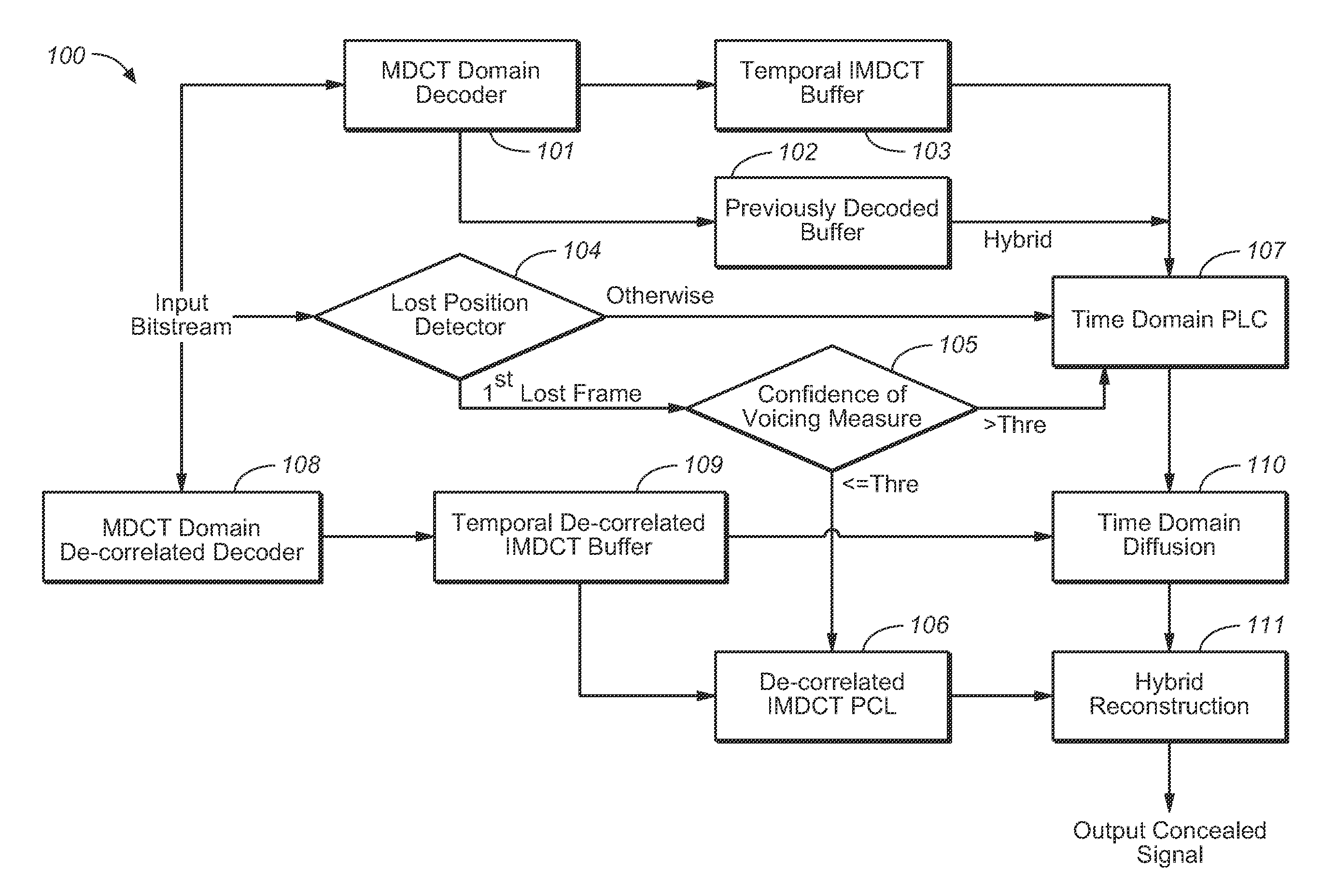
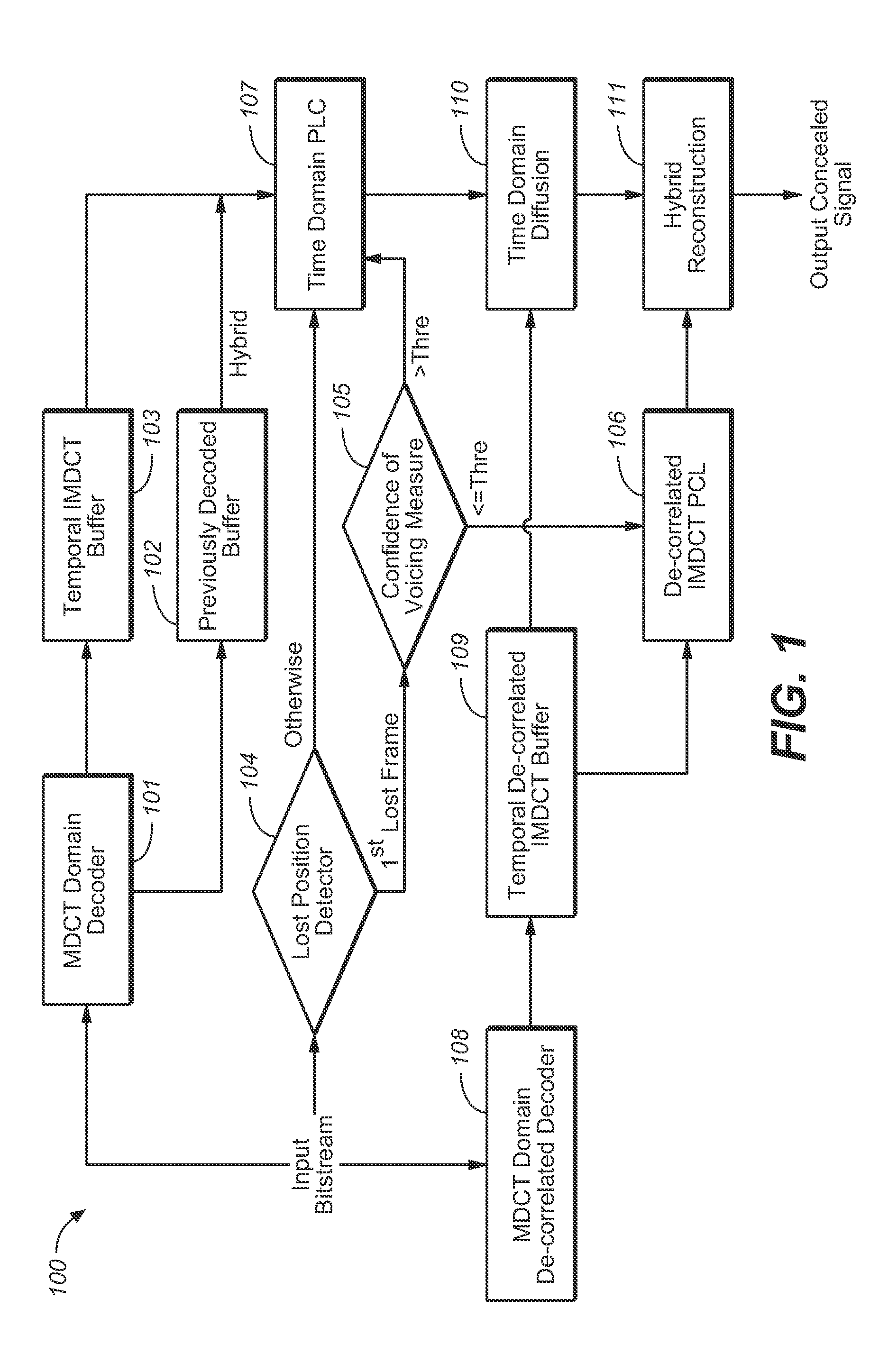
[0045]As outlined in the background section, PLC schemes tend to insert artifacts into a concealed audio signal, notably for an increasing number of consecutively lost packets. In the present document, various measures for improving PLC are described. These measures are described in the context of an overall PLC system 100 (see FIG. 1). It should be noted, however, that these measure may be used standalone or in arbitrary combination with one another.

[0046]The PLC system 100 will be described in the context of a MDCT based audio encoder, such as e.g. an AAC (Advanced Audio Coder). It should be noted, however, that the PLC system 100 is also applicable in conjunction with other transform-based audio codecs and / or other time domain to frequency domain transforms (in particular to other overlapped transforms).

[0047]In the following, an AAC encoder is described in further detail. The AAC core encoder typically breaks an audio signal 302 (see FIG. 3) into a sequence of segments 303, call...


PUM


Abstract

The present document relates to audio signal processing in general, and to the concealment of artifacts that result from loss of audio packets during audio transmission over a packet-switched network, in particular. A method (200) for concealing one or more consecutive lost packets is described. A lost packet is a packet which is deemed to be lost transform-based audio decoder. Each of the one or more lost packets comprises a set of transform coefficients. A set of transform coefficients is used by the transform-based audio decoder to generate a corresponding frame of a time domain audio signal. The method (200) comprises determining (205) for a current lost packet of the one or more lost packets a number of preceding lost packets from the one or more lost packets; wherein the determined number is referred to as a loss position. Furthermore, the method comprises determining a packet loss concealment, referred to as PLC, scheme based on the loss position of the current packet; and determining (204, 207, 208) an estimate of a current frame of the audio signal using the determined PLC scheme (204, 207, 208); wherein the current frame corresponds to the current lost packet.

Description

TECHNICAL FIELD OF THE INVENTION[0001]The present document relates to audio signal processing in general, and to the concealment of artifacts that result from loss of audio packets during audio transmission over a packet-switched network, in particular.BACKGROUND OF THE INVENTION[0002]Packet loss occurs frequently in VoIP or wireless voice communication systems. Lost packets result in clicks or pops or other artifacts that greatly degrade the perceived speech quality at the receiver side. To combat the adverse impact of packet loss, packet loss concealment (PLC) algorithms, also known as frame erasure concealment algorithms, have been described. Such algorithms normally operate at the receiver side by generating a synthetic audio signal to cover missing data (erasures) in a received bit stream. Among various PLC methods, time domain pitch-based waveform substitution, such as G.711 Appendix I (ITU-T Recommendation G.711 Appendix I, “A high quality low complexity algorithm for packet ...

Claims


Application Information

Patent Timeline
Patent Type & Authority Applications(United States)
IPC IPC(8): G10L19/00
CPCG10L19/0017G10L19/005
Inventor HUANG, SHENSUN, XUEJING
Owner DOLBY LAB LICENSING CORP
Why Eureka
Try Eureka