Photo-voltaic device having improved shading degradation resistance

a photovoltaic device and degradation resistance technology, applied in the direction of pv power plants, sustainable buildings, instruments, etc., can solve the problems of increasing the cost and complexity of the device, still subject to incident light, and the number of bypass diodes required to completely avoid the possibility of reverse bias occurren

Inactive Publication Date: 2015-09-10
DOW GLOBAL TECH LLC
View PDF4 Cites 2 Cited by
  • Summary
  • Abstract
  • Description
  • Claims
  • Application Information

AI Technical Summary

Problems solved by technology

When a solar module is subjected to partial shading, a situation potentially occurs where a portion of the PV area of a series circuit is shaded and other portions of the same series circuit are still subject to incident light.
However, the number of bypass diodes required to completely avoid the possibility of a reverse bias occurrence can be quite high, especially in thin-film applications where the reverse breakdown voltage of the cells can be relatively low compared to other applications.
A high number of bypass diodes increases the cost and complexity of the device, and can reduce the usable area of the device for solar energy collection as accommodation is made for the inclusion of the diodes.
A reduction of the number of bypass diodes from the number required to avoid the possibility of reverse bias introduces the risk that individual PV areas will experience reverse bias.
PV areas that are exposed to reverse bias suffer short term power reductions even after light is re-introduced, and can experience longer term or permanent degradation.

Method used


Image

  • Photo-voltaic device having improved shading degradation resistance
  • Photo-voltaic device having improved shading degradation resistance
  • Photo-voltaic device having improved shading degradation resistance

Examples


Embodiment Construction

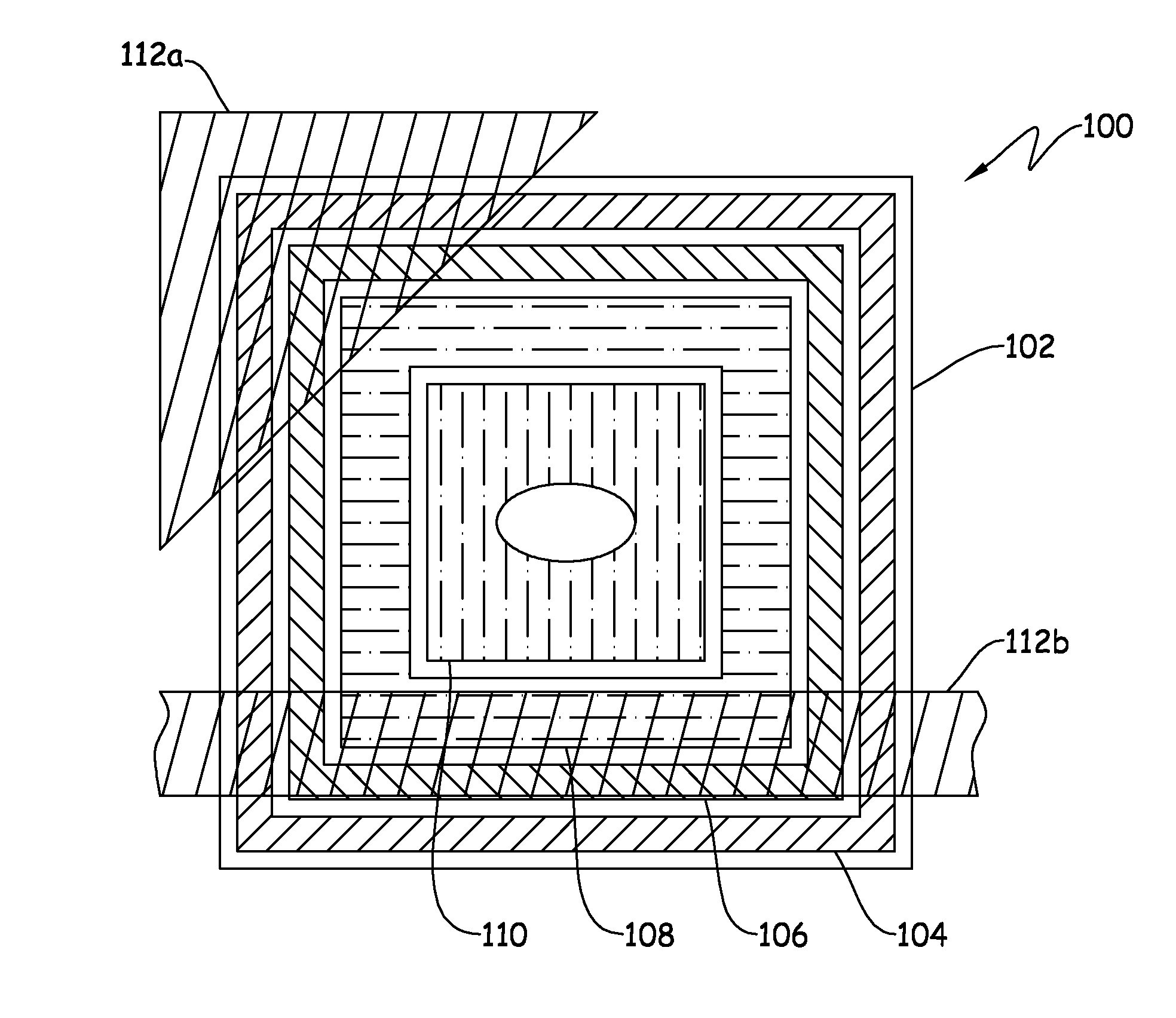
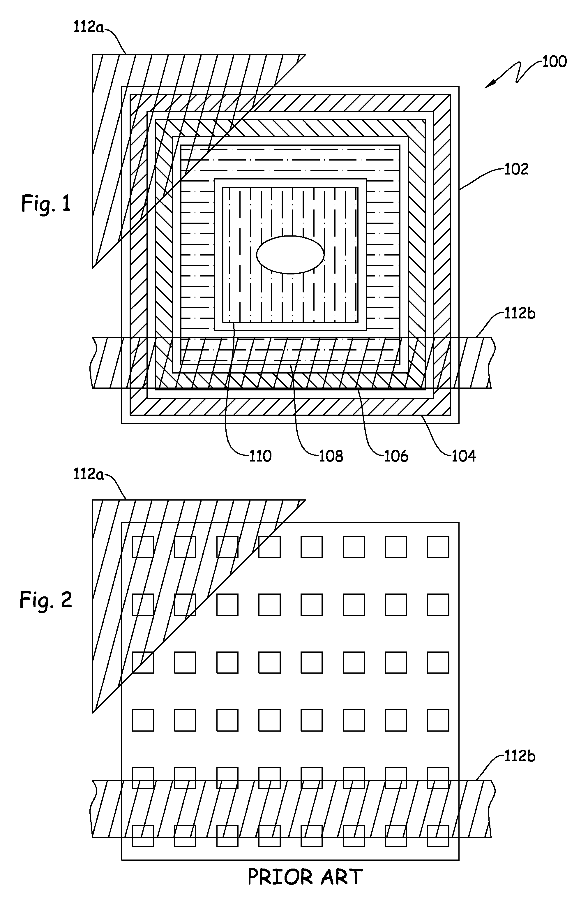
[0018]Referencing FIG. 1, a photovoltaic (PV) device 100 is schematically represented. The PV device 100 includes an active solar area 102 that defines a number of PV cell sets. Each PV cell set includes one or more PV cells. Where multiple PV cells form a PV cell set, the PV cells forming the PV cell set are coupled in a parallel electrical configuration. The PV device 100 includes four PV cell sets, 104, 106, 108, 110. The PV cell sets 104, 106, 108, 110 are arranged in a concentric framing arrangement. The concentric framing arrangement includes outer ones of the PV cell sets 104, 106, 108, 110 being positioned further from a geometric center of the active solar area 102. An outer concentric framing PV cell set may be positioned fully or partially outside of the inner concentric framing PV cell set (e.g. PV cell set 104 is positioned fully outside PV cell set 106). The concentric framing arrangement provides a favorable robustness to shading induced reverse biasing for a wide var...


PUM


Abstract

An article of manufacture includes an active solar area having a number of photovoltaic (PV) cell sets. Each of the PV cell sets includes one or more PV cells, and has a PV cell set area. Each of the PV cell sets includes a spacing distribution, where the spacing distribution is such that a geometric shape having a predetermined characteristic area value cannot be positioned to cover an area greater than a reverse biasing fraction of the PV cell set area corresponding to the PV cell set.

Description

FIELD[0001]The present invention relates to improved photo-voltaic devices, and more particularly but not exclusively relates to photo-voltaic devices having an improved resistance to shading induced degradation.INTRODUCTION[0002]Installed solar modules, for example within a building integrated photovoltaic (BIPV) device, are subject to partial shading from time to time. When a solar module is subjected to partial shading, a situation potentially occurs where a portion of the PV area of a series circuit is shaded and other portions of the same series circuit are still subject to incident light. Shaded portions of the PV area that are in series with illuminated portions of the PV area are subject to the possibility that the shaded portions will be subject to a reverse voltage bias. Presently known solar modules can manage the reverse bias situation by utilizing bypass diodes. However, the number of bypass diodes required to completely avoid the possibility of a reverse bias occurrenc...

Claims


Application Information

Patent Timeline
Patent Type & Authority Applications(United States)
IPC IPC(8): H01L31/0475G06F17/50
CPCG06F17/5072H01L31/0475H01L31/0504Y02E10/50Y02B10/10G06F30/392
Inventor NAMJOSHI, ABHIJITMCKEEN, JOHNFEIST, REBEKAH
Owner DOW GLOBAL TECH LLC
Why Eureka
Try Eureka