Battery cell comprising a housing covering plate having a raised central region

a battery cell and central region technology, applied in the field of battery cells, can solve the problem of unexpected short circuits in the case of battery cells

Active Publication Date: 2015-09-10
ROBERT BOSCH GMBH
View PDF4 Cites 8 Cited by
  • Summary
  • Abstract
  • Description
  • Claims
  • Application Information

AI Technical Summary

Benefits of technology

[0007]With the aid of embodiments of the present invention, it is possible to reduce, inter alia, the risk of short circuits in battery cells.
[0010]In the case of housings for conventional battery cells, a covering plate closing off the opening of the container is generally flat. The covering plate can be stamped out of a metal sheet for this purpose in such a way that an outer contour of the stamped-out covering plate substantially corresponds to the inner cross section of the container in the region of the opening. Thus, the outer rim of the covering plate can be welded easily and in hermetically seal tight fashion to the inner surface of the wall of the container. In addition, through-holes are stamped out in the covering plate, with the electrically conductive contact arrangements being passed through said through-holes in each case from the interior of the housing where they are electrically connected to one of the current collectors outwards out of the housing, where they can form one of the terminal contacts of the battery cell.
[0013]The central region can extend at least beyond a subregion of the covering plate, wherein this subregion extends from a contact arrangement forming a positive terminal to a contact arrangement forming a negative terminal. In other words, the central region is intended to extend at least in a subregion of the covering plate in which collecting water could otherwise result in a short circuit between the two contact arrangements. Owing to the fact that the central region is raised in comparison with the peripheral region, it is possible to avoid a situation in which water accumulates there. Instead, water can flow away from the central region which is raised in the form of a platform laterally towards the lower peripheral region, where it cannot effect a short circuit.
[0014]The covering plate comprising a central region and a peripheral region running on different levels can be produced, for example, by means of embossing of a metal sheet. In this case, the central region itself can be flat and possibly a transition towards the lower peripheral region can be rounded off in order to facilitate the flow of moisture away from the central region towards the peripheral region. Alternatively, the central region can also be outwardly convex, so that a center of the central region protrudes beyond the peripheral region further outwards than a rim of the central region. In this way, water is further assisted in flowing away from the central region towards the peripheral region. In particular, a rounded transition between the central region and the peripheral region can have a supporting effect in respect of this flowing away of water.
[0015]The peripheral region can form a channel which reaches inwards into the opening of the container and which can act as a water collection channel. Water flowing away from the central region can therefore flow into the channel and evaporate there over time. This makes it possible to prevent the water from flowing towards adjacent battery cells, for example, and causing damage there or from pouring into a housing surrounding a battery cell, as a result of which corrosion could arise there.
[0016]The channel can have a U-shaped cross section. An inner flank of the channel, i.e. a flank of the channel which becomes the inner central region, can in this case be higher than an outer flank. This makes it possible for water which collects in the channel to not be able to arrive at the central region since it can flow away before this via the lower outer flank.

Problems solved by technology

It has been observed that unexpected short circuits can arise in the case of battery cells, in particular in moist operating conditions.

Method used


Image

  • Battery cell comprising a housing covering plate having a raised central region
  • Battery cell comprising a housing covering plate having a raised central region
  • Battery cell comprising a housing covering plate having a raised central region

Examples


Embodiment Construction

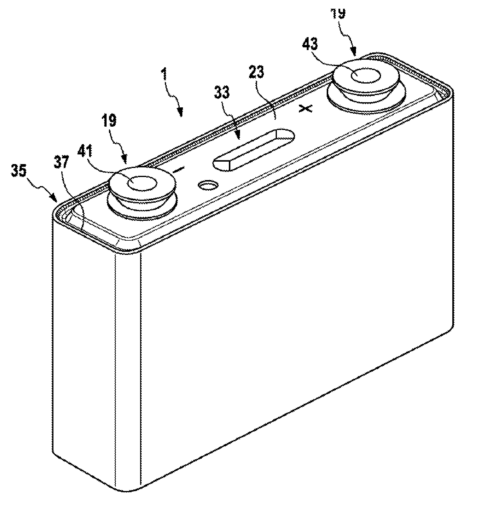
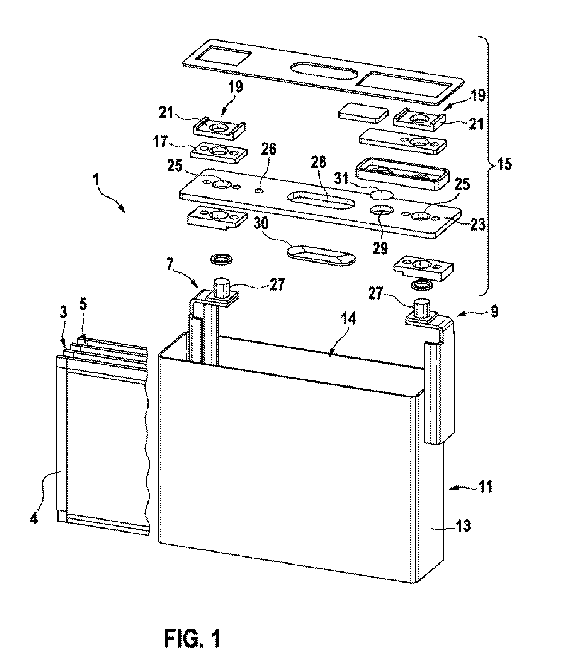
[0027]FIG. 1 shows a conventional lithium-ion battery cell in an exploded view. It can be seen that the battery cell comprises a large number of individual components, which are provided separately and need to be assembled in a complex manner during manufacture. Only the component parts which are necessary for the understanding of embodiments of the invention and the features thereof are described herein, and no description is provided of the remaining component parts of the battery cell.

[0028]The battery cell 1 has a coil element 3 comprising a wound stack 5 comprising a copper film, which is coated with anode material, and an aluminum film, which is coated with cathode material, and plastic films therebetween, which act as diaphragms.

[0029]For electrical contact-making, the copper film and the aluminum film are stacked one on top of the other with a slight offset along the winding axis in the opposite direction so that the copper film on one narrow side and the aluminum film on an...


PUM

PropertyMeasurementUnit
electrically conductivelyaaaaaaaaaa
electrically conductiveaaaaaaaaaa
electrical energyaaaaaaaaaa

Abstract

The invention relates to a battery cell, in particular a lithium-ion battery cell, wherein a cover plate (23) forming a part of a battery cell housing, which is designed as a plane sheet in a conventional manner, is modified to avoid short circuits between the poles of the battery cell due to moisture, for example. To this end, the cover plate (23) is provided with a central area (33) and an edge area (35) surrounding said central area (33). The central area (33) is located above an opening (14) to be closed off by the cover plate (23) of a container (13) forming a part of the battery cell housing, whereas the edge area (35) extends inside said opening (14). Thus, occurring moisture can drain off the platform-like raised central area (33) sideways toward a channel (37) in the edge area (35), and evaporate from there.

Description

BACKGROUND OF THE INVENTION[0001]The present invention relates to a battery cell, in particular a lithium-ion battery cell. In addition, the invention relates to a motor vehicle comprising such a battery cell.[0002]Battery cells, sometimes also referred to as rechargeable battery cells, are used for the chemical storage of energy provided electrically. Already today battery cells are used for supplying energy to a large number of mobile devices. In the future, battery cells are intended to be used, inter alia, for supplying energy to mobile electric vehicles or hybrid vehicles, on land and in water, and for the stationary buffer-storage of electrical energy originating from alternative energy sources.[0003]For this purpose, usually a large number of battery cells are assembled to form battery packs. In order to use a pack volume available in this case in a manner which is as efficient as possible, primarily battery cells having a prismatic, for example a right-parallelepipedal form ...

Claims


Application Information

Patent Timeline
Patent Type & Authority Applications(United States)
IPC IPC(8): H01M2/04H01M2/06H01M10/04H01M50/15H01M50/176
CPCH01M2/0456H01M10/0431H01M2220/20H01M2/043H01M2/06H01M50/169H01M50/15H01M50/176Y02E60/10Y02P70/50
Inventor FEIGL, MARKUS
Owner ROBERT BOSCH GMBH
Why Eureka
Try Eureka