Motor drive device having insulation resistance detecting function and method of detecting insulation resistance of motors

a technology of motor drive and insulation resistance, which is applied in the direction of motor/generator/converter stopper, dynamo-electric converter control, instruments, etc., can solve the problems of reducing the measurement accuracy of specific motors, increasing leakage current through semiconductor switching elements, and reducing the measurement accuracy of insulation resistan

Active Publication Date: 2015-09-10
FANUC LTD
View PDF4 Cites 28 Cited by
  • Summary
  • Abstract
  • Description
  • Claims
  • Application Information

AI Technical Summary

Benefits of technology

[0063]FIG. 13 is a flow chart for explaining the processing steps of an insulation resistance detecting method using a motor drive device according to the third embodiment of the present invention; an

Problems solved by technology

However, the prior art methods described in Patent Document 1 and Patent Document 2 entail the problem that when, in the motor drive device including a plurality of inverter units that drive a plurality of motors, a specific detection-target motor is selected from plural motors to measure insulation resistance, if even one of the motors other than the detection target is low in insulation resistance, the measurement accuracy lowers in a high-temperature condition under which leakage current through semiconductor switching elements increases.
As a result, in particular, when the motor drive device have a large number of motors connected to hereto and if the insulation resistances of the motors other than the target for measurement are lowered, there occurs the problem that the measurement accuracy in the insulation resistance measurement of the specific motor to be measured markedly lowers in a high-temperature condition under which leakage currents through semiconductor switching elements increase.
In general, the reason why increase of leakage current ICES in IGBTs for use in inverters for motor drive is regarded as a problem is mainly in view of loss increase.
However, when IGBTs in the inverter unit are used as the selector switches for the motor to be measured on insulation resistance as in the prior art disclosed in Patent Document 1 and Patent Document 2, even a leakage current ICES as low as a level of some tens μA, which will not cause any problem in view of loss, will cause degradation of measurement accuracy in the prior art measurement of insulation resistance of motors.
However, since the actual semiconductor switching element even in its off-state will permit leakage current to flow at a level that affects

Method used


Image

  • Motor drive device having insulation resistance detecting function and method of detecting insulation resistance of motors
  • Motor drive device having insulation resistance detecting function and method of detecting insulation resistance of motors
  • Motor drive device having insulation resistance detecting function and method of detecting insulation resistance of motors

Examples


first embodiment

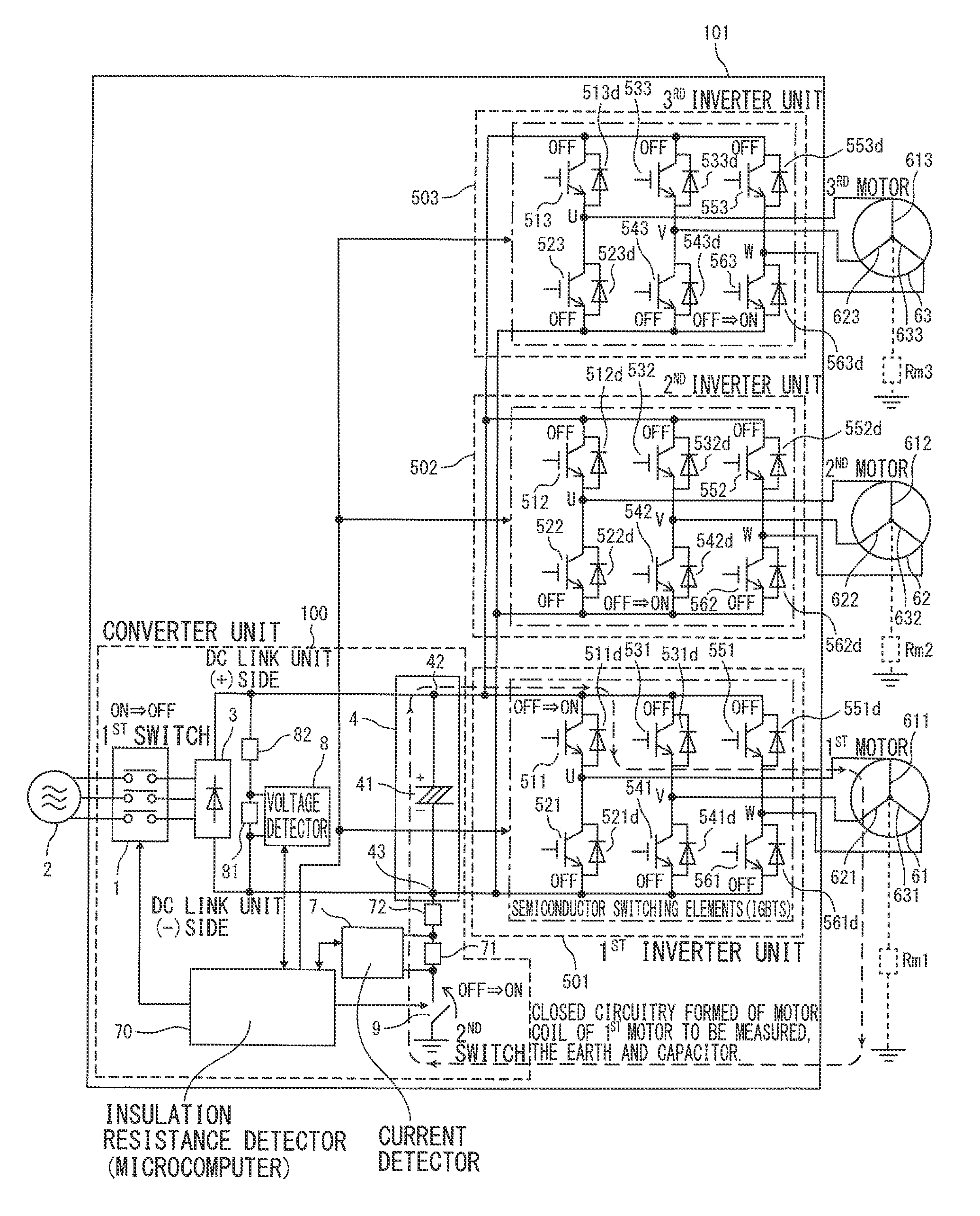
[0066]To begin with, a motor drive device according to a first embodiment of the present invention will be described. FIG. 5 is a configurational diagram of a motor drive device including an insulation resistance detector according to the first embodiment of the present invention.

[0067]A motor drive device 101 according to the first embodiment of the present invention includes: a converter unit 100 having a rectifier circuit 3 configured to rectify AC voltage supplied from an AC power supply 2 via a first switch 1 into DC voltage; a power supply unit 4 configured to smooth the DC voltage rectified by the rectifier circuit 3 through a capacitor 41; a plurality of inverter units 501 to 503 configured to convert the DC voltage from the power supply unit 4 to AC voltage to drive multiple motors 61 to 63, respectively, by switching operation of the semiconductor switching elements (511, 531, 551, 512, 532, 552, 513, 533, 553) in an upper arm, connected between a positive-side terminal of...

second embodiment

[0108]Next, a motor drive device according to a second embodiment of the present invention will be described. FIG. 11 is a configurational diagram of a motor drive device including an insulation resistance detector according to the second embodiment of the present invention.

[0109]A motor drive device 102 according to the second embodiment of the present invention includes: a converter unit 100 having a rectifier circuit 3 configured to rectify AC voltage supplied from an AC power supply 2 via a first switch 1 into DC voltage; a power supply unit 4 configured to smooth the DC voltage rectified by the rectifier circuit 3 through a capacitor 41; a plurality of inverter units 501 to 503 that convert the DC voltage from the power supply unit 4 to AC voltage to drive multiple motors 61 to 63, respectively, by switching operation of the semiconductor switching elements in an upper arm, connected between the positive-side terminal of the capacitor 41, i.e., the DC link unit plus-side termin...

third embodiment

[0131]Next, a motor drive device according to a third embodiment of the present invention will be described. The configuration of the motor drive device of the third embodiment is the same as that of the motor drive device according to the first embodiment.

[0132]A motor drive device according to the third embodiment of the present invention includes: a converter unit 100 having a rectifier circuit 3 configured to rectify AC voltage supplied from an AC power supply 2 via a first switch 1 into DC voltage; a power supply unit 4 configured to smooth the DC voltage rectified by the rectifier circuit 3 through a capacitor 41; a plurality of inverter units 501 to 503 configured to convert the DC voltage from the power supply unit 4 to AC voltage to drive multiple motors 61 to 63, respectively, by switching operation of the semiconductor switching elements in an upper arm, connected between a positive-side terminal of the capacitor 41, i.e., the DC link unit plus-side terminal 42 and a moto...


PUM


Abstract

A motor drive device includes: a converter; a power supply; a plurality of inverter units configured to convert DC to AC to drive a plurality of motors by upper arm switching elements connected between a capacitor and motor coils and lower arm switching elements connected between the capacitor and motor coils; a second switch configured to connect the capacitor to the earth; a current detector configured to measure current flowing between the capacitor and the earth; a voltage detector configured to measure the voltage across the capacitor; and, an insulation resistance detector configured to detect insulation resistance of the multiple motors based on the current and voltage measured in a condition that the switching element to which the motor coil to be measured is connected is turned on and the switching elements to which a motor coil other than the target for measurement is connected are turned off.

Description

CROSS-REFERENCE TO RELATED APPLICATIONS[0001]This application is a new U.S. patent application that claims benefit of JP 2014-043136, filed on Mar. 5, 2014, the entire content of JP 2014-043136 is hereby incorporated by reference.FIELD OF THE INVENTION[0002]The present invention relates to a motor drive device and a method of detecting insulation resistance of motors, in particular relating to a motor drive device having functions of correctly measuring and detecting insulation resistance of motors as well as a method of detecting insulation resistance of motors, without receiving influence from currents flowing through semiconductor switching elements in inverter unitsBACKGROUND OF THE INVENTION[0003]Conventionally, there have been known motor drive devices that have a function of detecting insulation resistance of motor winding by applying a voltage charged on a smoothing capacitor in a direct current (DC) link unit, between the motor winding (coil) and the earth (e.g., Japanese P...

Claims


Application Information

Patent Timeline
IPC IPC(8): H02P27/06
CPCH02P27/06B60L3/0061B60L3/0069B60L3/04B60L15/007B60L2210/30B60L2240/425B60L2240/427B60L2240/429B60L2240/525B60L50/51G01R27/025G01R31/346G01R31/52H02M5/458H02P5/74H02M1/0009H02M1/008Y02T10/64Y02T10/70Y02T10/72Y02T10/7072Y02T90/12Y02T90/14
Inventor TATEDA, MASAYASATO, HIROYASUHIRAI, AKIRA
Owner FANUC LTD
Why Eureka
Try Eureka