Microfluidic circuit allowing drops of several fluids to be brought into contact, and corresponding microfluidic method

a microfluidic circuit and fluid drop technology, applied in the direction of positive displacement liquid engines, water supply installations, laboratory glassware, etc., can solve the problems of ineffective method for observation of very fast reactions, high cost, and inability to analyze the progress of reactions, etc., to achieve the effect of simplifying production

Active Publication Date: 2015-09-17
ECOLE POLYTECHNIQUE +1
View PDF3 Cites 58 Cited by
  • Summary
  • Abstract
  • Description
  • Claims
  • Application Information

AI Technical Summary

Benefits of technology

[0040]The walls of said microchannel portion of the second drop forming device diverging so as to detach a drop of the second solution under the effect of the surface tension of the second solution; and said second means for guiding said drops comprising portions of wall of said microchannels, diverging so...

Problems solved by technology

This fast mixing of the components in a tank and the analysis of the progress of the reaction require specialist equipment items, which are costly.
Moreover, implementing this method leads to the consumption of a relatively significant quantity of the reagents (generally more than 100 microliters), which may prove costly when one of the reagents is rare or precious or when a series of numerous analyses is necessary.
Finally, this method proves ineffective for the observation of very fast reactions, which take place while the reagents are being mixed.
Howeve...

Method used


Image

  • Microfluidic circuit allowing drops of several fluids to be brought into contact, and corresponding microfluidic method
  • Microfluidic circuit allowing drops of several fluids to be brought into contact, and corresponding microfluidic method
  • Microfluidic circuit allowing drops of several fluids to be brought into contact, and corresponding microfluidic method

Examples


Embodiment Construction

6.1. Microfluidic Circuit

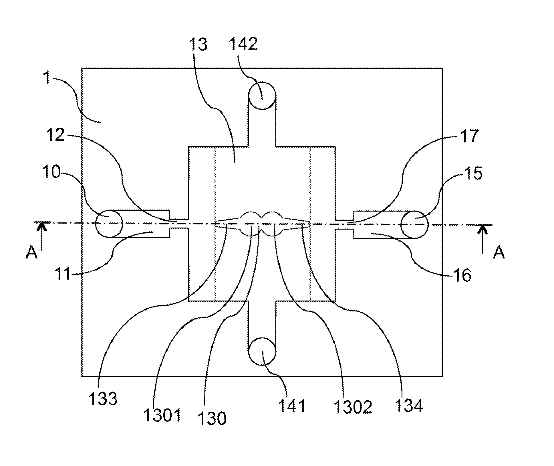
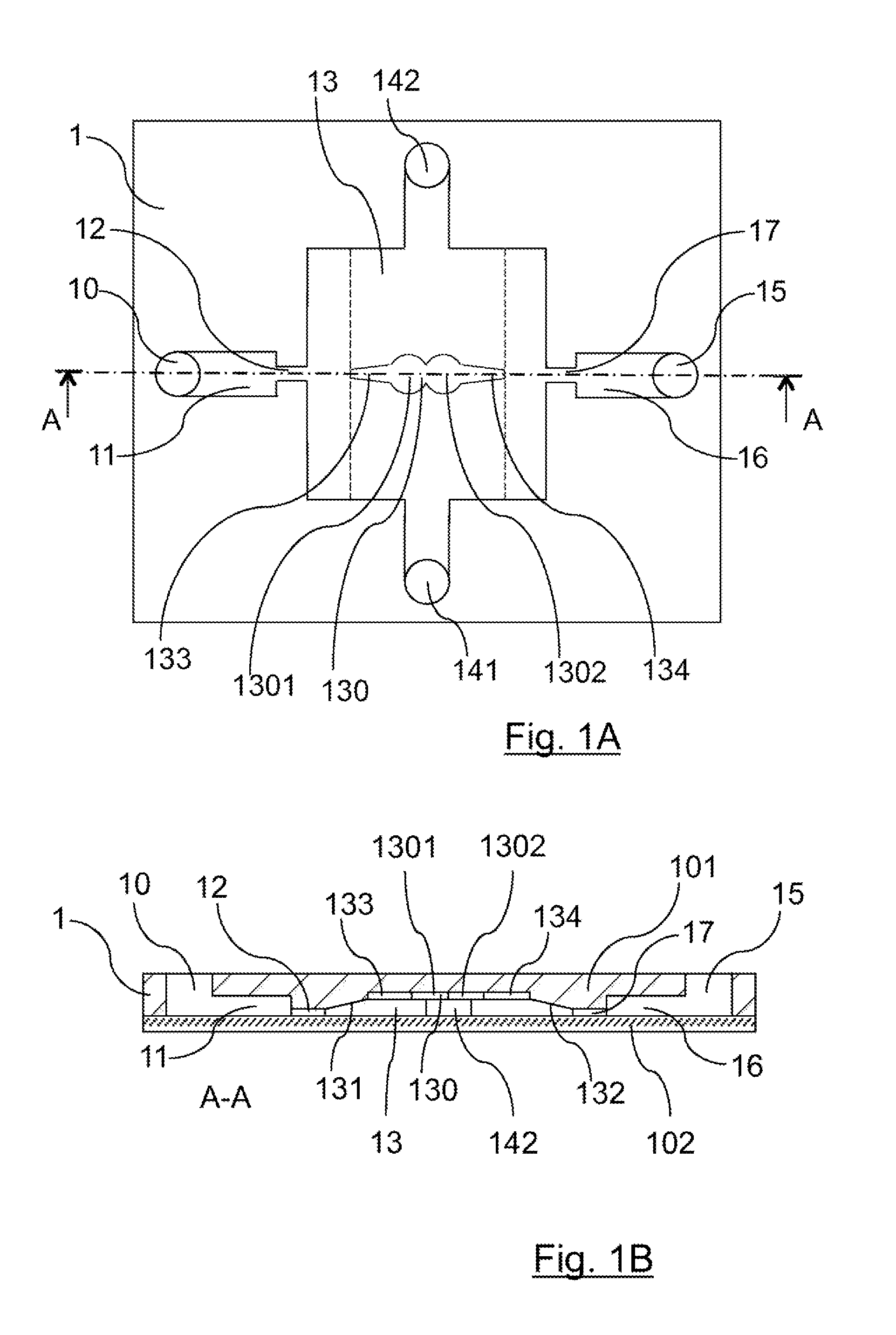
[0075]FIG. 1A is a plan, in plan view, of a microfluidic circuit 1 according to a first embodiment of the invention, making it possible to bring drops of several fluids into contact. This plan shows the different microfluidic channels which are formed inside this microfluidic circuit. This microfluidic circuit is also represented, in cross-sectional view, in FIG. 1B.

[0076]As is known per se, the microfluidic circuit may consist of two superposed plates, bonded to one another. Thus, the circuit 1 consists of a plate 102, which may for example be a transparent microscope slide, and a plate 101, of which the face in contact with the plate 102 is etched so as to define microchannels between the two plates, which are superposed and bonded to one another. The plate 101 may be made of a polymer material. Preferably, the material constituting at least one of the two plates is transparent, in order to facilitate the observation of the fluids in the microchannels. In ...


PUM

PropertyMeasurementUnit
Flow rateaaaaaaaaaa
Sizeaaaaaaaaaa
Areaaaaaaaaaaa

Abstract

The subject of the present invention is a microfluidic circuit in which are defined microchannels able to contain fluids and including at least one device for forming drops of a solution, guiding the drops to a storage zone in which one of the drops can be brought into contact with a drop of another solution, the walls of the microchannel portion forming the first drop-formation device diverging so as to cause drops of the first solution to detach under the effect of the surface tension of the first solution; the first guide include wall portions of the microchannels that diverge so as to cause the drops to move along under the effect of the surface tension of the first solution.

Description

1. FIELD OF THE INVENTION[0001]The present invention relates to a microfluidic circuit allowing for the manipulation of very small quantities of fluids. It relates in particular to such a microfluidic circuit that allows several different fluids to be manipulated and brought into contact.[0002]The present invention relates in particular to such a microfluidic circuit allowing small quantities of chemical reagents to be brought into contact to trigger a reaction between them and conduct a kinetic analysis of this reaction.[0003]The invention relates also to a microfluidic method for bringing drops of several fluids into contact.2. PRIOR ART“Stop Flow” Methods[0004]Different methods are known to those skilled in the art for analyzing the kinetics of a chemical reaction. One of these methods consists in mixing reagents in a tank and in observing, in the moments following the mixing, the trend of the chemical reaction. The application of this method demands a particularly fast mixing of...

Claims


Application Information

Patent Timeline
IPC IPC(8): B01L3/00
CPCB01L3/5027B01L2200/10B01L2300/0867B01L2400/02B01L2300/089B01L2200/16B01L3/502784B01L3/502792B01L2200/0673B01L2300/0816B01L2400/0487B01L2400/0688B01L2400/086Y10T137/0318B01F23/40B01F31/31B01F31/86B01F33/3033B01F33/3031B01F33/3021B01F33/811B01F35/715
Inventor BAROUD, CHARLESABBYAD, PAULFRADET, ETIENNEDANGLA, REMI
Owner ECOLE POLYTECHNIQUE
Why Eureka
Try Eureka