Method and System for Installing Fasteners with Electromagnetic Effect Protection

Active Publication Date: 2015-09-17
THE BOEING CO
View PDF4 Cites 4 Cited by
  • Summary
  • Abstract
  • Description
  • Claims
  • Application Information

AI Technical Summary

Benefits of technology

[0015]In yet another illustrative embodiment, a method for installing a fastener is presented. The fastener may be positioned within a cooling system associated with a robotic device. The cooling system may be configured to cool the fastener prior to installing the fastener using the robotic device. The fastener may be selected from one of a bolt, a screw, a hexdrive, an interference fit fastener, a rivet, a lockbolt, and a tapered sleeved bolt. A top portion of the fastener may be cooled using at least one of dry ice, liquid nitrogen, a refrigerant, a cooler, a refrigeration unit, or cooled air to stiffen the top portion. The top portion of the fastener may include a dielectric material selected from at least one of a polymer, a thermoplastic material, a thermoset material, an adhesive, or rubber. The dielectric material may be configured to provide electromagnetic effect protection. The fastener may be cooled to a temperature such that the top portion of the fastener may have a desired level of stiffness. The fastener may be installed in a structure using a rivet gun associated with the robotic device after cooling such that deformation in the top portion of the fastener may be reduced when installed in the structure in an aircraft.
[0016]In still another illustrative embodiment, a fastener installation system may comprise a fastener having a t

Problems solved by technology

Some of these conditions may result in undesirable electromagnetic effects.
Composite structures in the aircraft may not conduct the electrical currents and electromagnetic forces generated by these conditions away from the structures in a desired manner.
In other illustrative examples, these electromagnetic effects may have an undesirable effect on composite structures, systems within

Method used


Image

  • Method and System for Installing Fasteners with Electromagnetic Effect Protection
  • Method and System for Installing Fasteners with Electromagnetic Effect Protection
  • Method and System for Installing Fasteners with Electromagnetic Effect Protection

Examples


Example

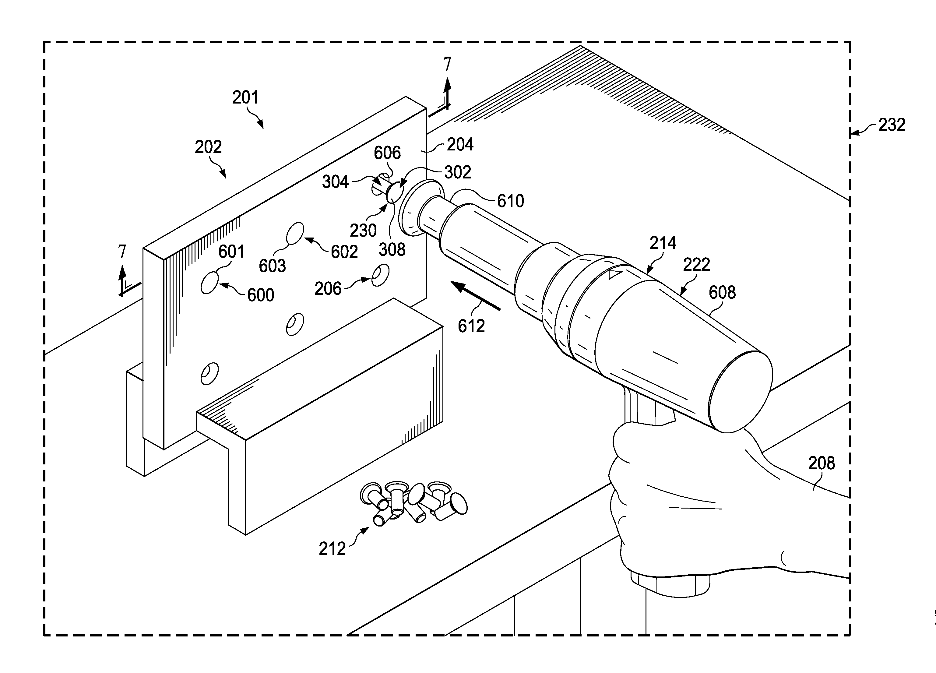
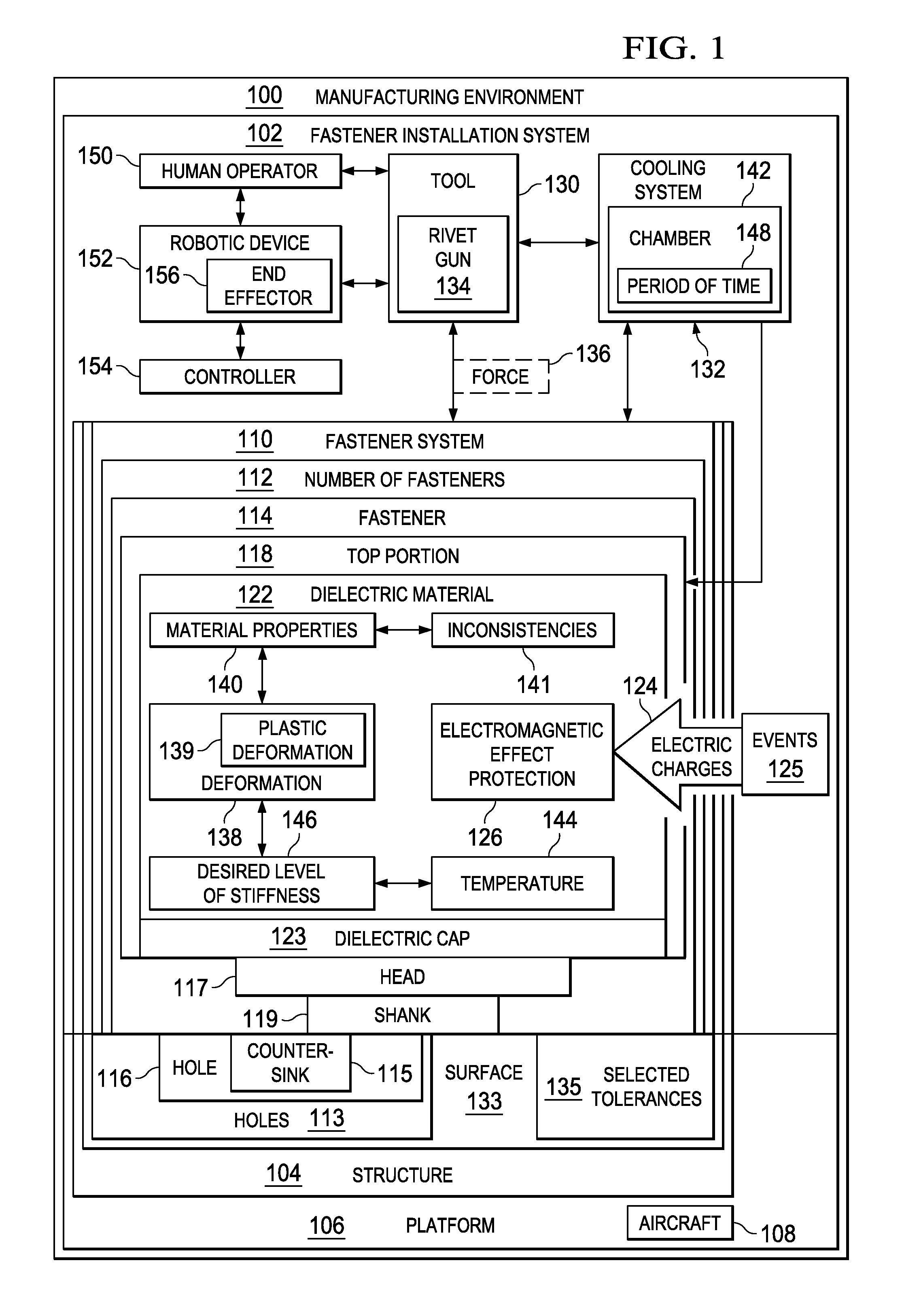
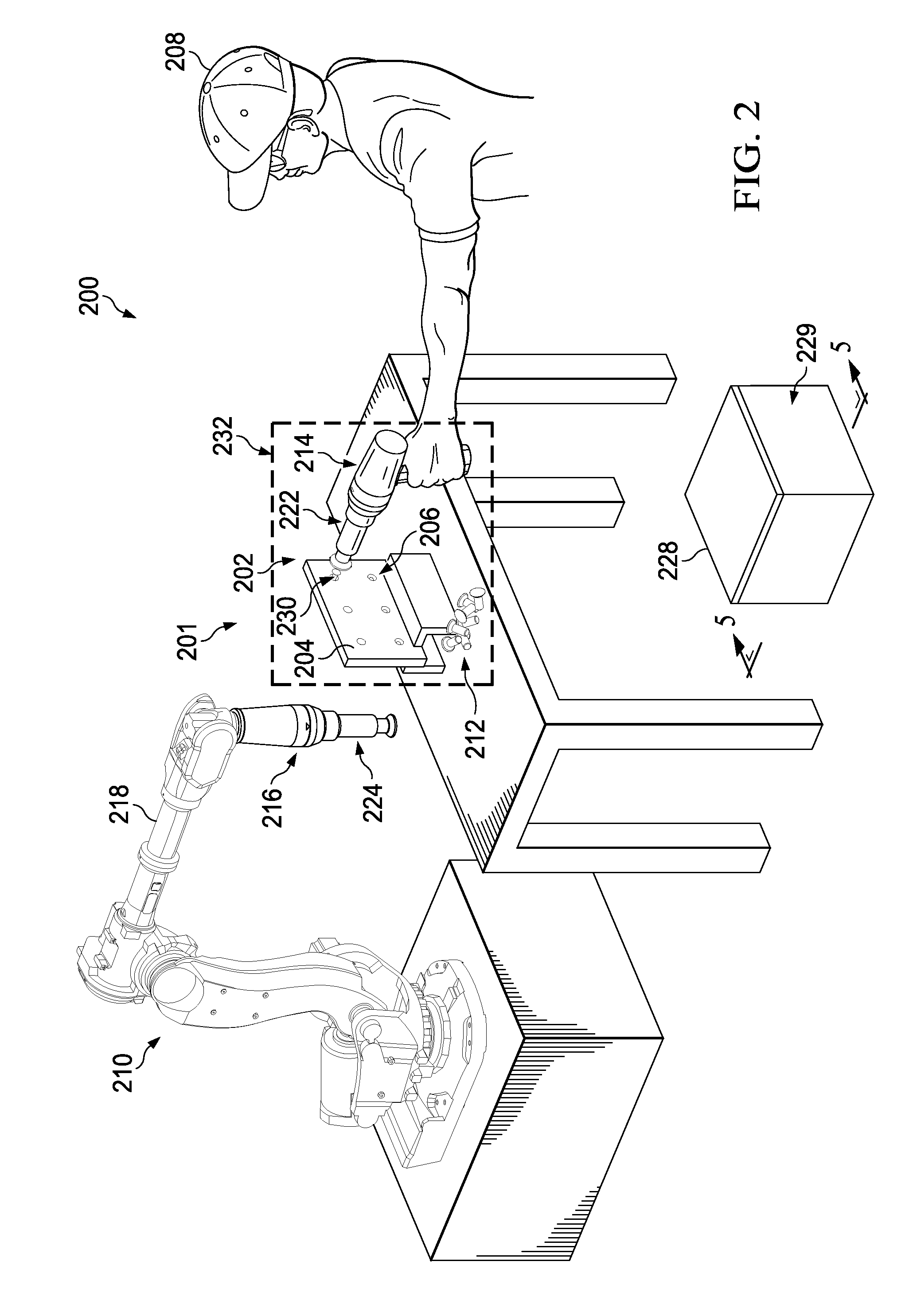
[0037]The illustrative embodiments recognize and take into account one or more different considerations. For example, without limitation, the illustrative embodiments recognize and take into account that it may be desirable to reduce or eliminate deformation in the dielectric material associated with the fastener head that may occur when a fastener with electromagnetic effect protection is installed in a composite structure. As an example, the illustrative embodiments recognize and take into account that the dielectric material used to provide electromagnetic effect protection may be softer or more prone to deformation than desired. As a result, some currently used methods for installing fasteners with electromagnetic event protection may cause deformation in the material.

[0038]The illustrative embodiments recognize and take into account that this deformation may be undesirable for various reasons. For instance, deformation of the top portion of the fastener may cause an uneven surf...


PUM

PropertyMeasurementUnit
Temperatureaaaaaaaaaa
Dielectric polarization enthalpyaaaaaaaaaa
Electric propertiesaaaaaaaaaa

Abstract

A method and system for installing a fastener. A fastener installation system comprises a fastener, a cooling system, and a tool. The fastener may have a top portion including a dielectric material. The cooling system may be configured to cool the top portion of the fastener to stiffen the top portion. The tool may be configured to install the fastener in a structure after cooling.

Description

CROSS-REFERENCE TO RELATED APPLICATION[0001]This application is related to the following U.S. patent application Ser. No. 13 / 434,835, filed Mar. 29, 2012, and entitled “Fastener Systems that Provide EME Protection,” which is incorporated herein by reference in its entirety.BACKGROUND INFORMATION[0002]1. Field[0003]The present disclosure relates generally to aircraft and, in particular, to manufacturing aircraft. Still more particularly, the present disclosure relates to a method and system for installing fasteners with electromagnetic effect protection in an aircraft.[0004]2. Background[0005]In manufacturing aircraft, different parts may be connected to each other to form aircraft structures. Aircraft structures may include, for example, without limitation, a wing and a fuselage of an aircraft. In some cases, these aircraft structures are formed from composite materials.[0006]A number of fasteners may be used to assemble composite structures, attach composite structures to the aircr...

Claims


Application Information

Patent Timeline
IPC IPC(8): B23P19/02B21J15/30B21J15/38B21J15/02
CPCB23P19/02B21J15/38B21J15/30B21J15/02B23P11/025B21J15/08B21J15/142B21J15/147F16B33/004Y10T29/49945Y10T29/53909
Inventor DREXLER, JULIE M.
Owner THE BOEING CO
Why Eureka
Try Eureka