
Method for manufacturing a component for a wind turbine

Inactive Publication Date: 2015-09-17
SIEMENS AG
View PDF6 Cites 1 Cited by
  • Summary
  • Abstract
  • Description
  • Claims
  • Application Information

AI Technical Summary

Benefits of technology

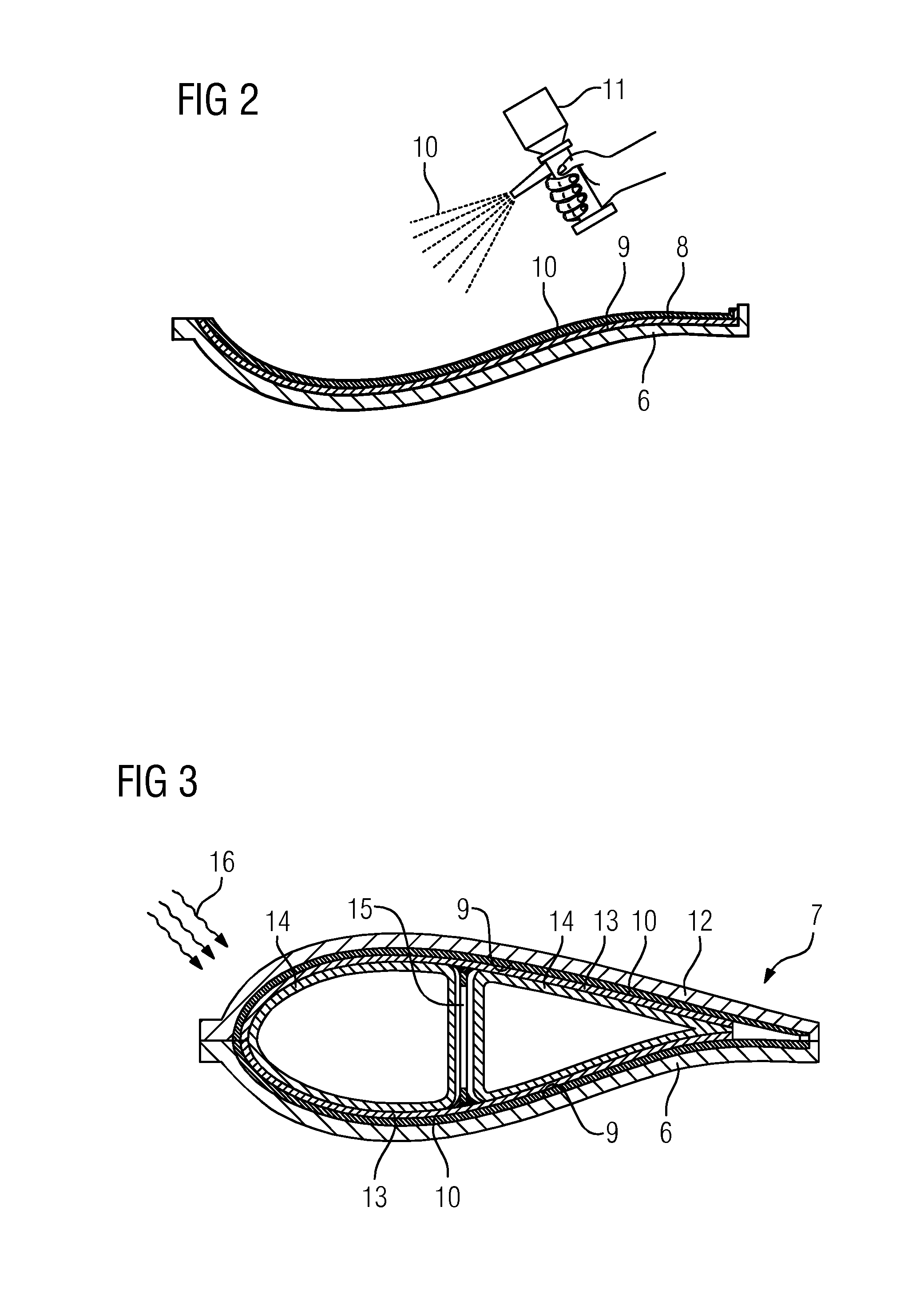
The present invention is about a method of protecting components during manufacturing processes. The method involves applying a peel-off layer, which acts as a release agent or can be used instead of a release agent. The peel-off layer prevents the release agent from sticking to the component and improves the quality of the component surface because sandblasting or sanding typically produces pinholes. The method can be carried out quickly and easily, and the operator can easily spot areas where the peel-off layer is not present, ensuring that the entire peel-off layer is removed.

Problems solved by technology

Even further, the release agent is known to have a negative effect on resin flow during the infiltration of the fiber material with the resin.

Method used


Image

  • Method for manufacturing a component for a wind turbine
  • Method for manufacturing a component for a wind turbine
  • Method for manufacturing a component for a wind turbine

Examples


Embodiment Construction

[0046]In the Figures, like reference numerals designate like or functionally equivalent elements, unless otherwise indicated.

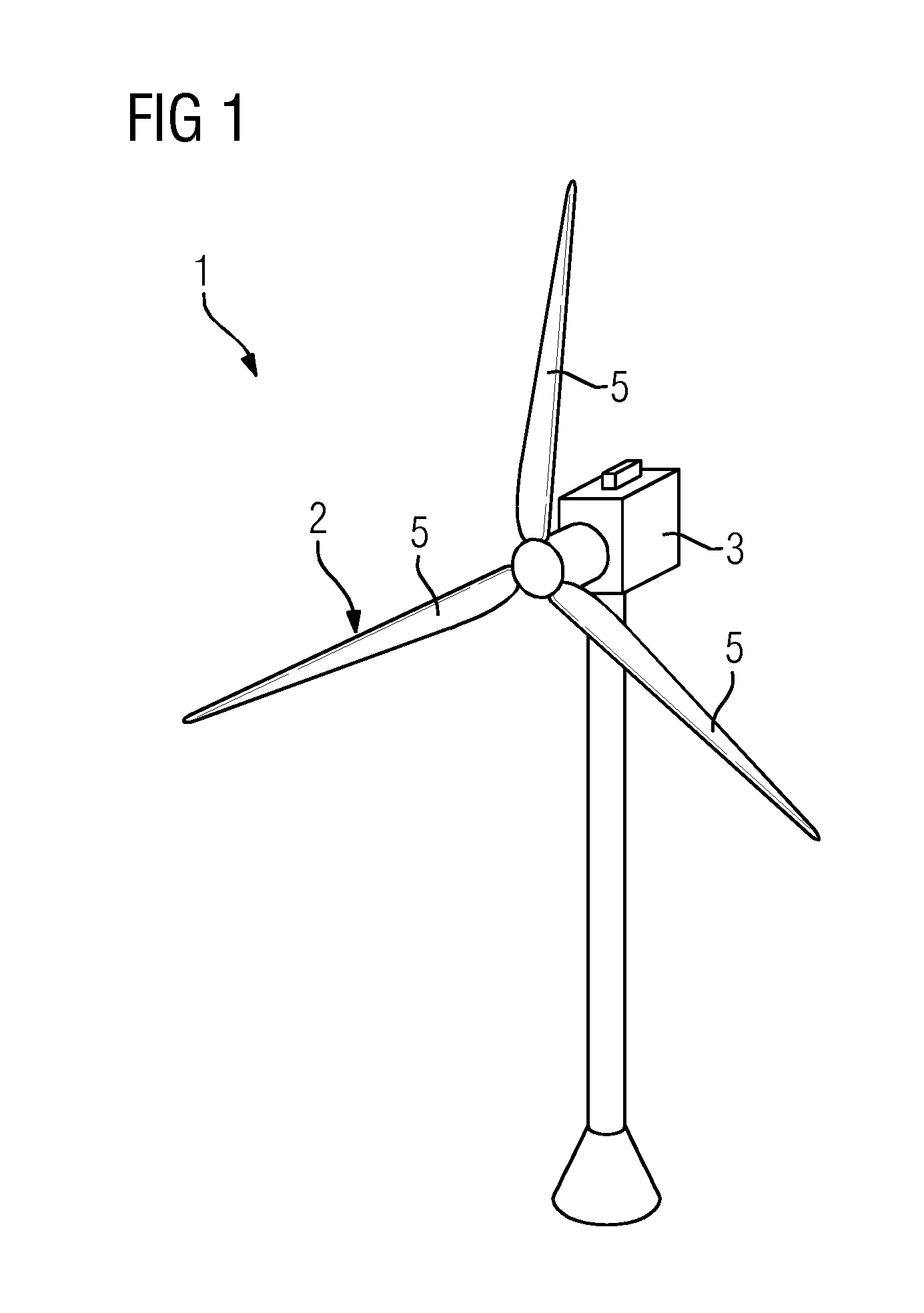
[0047]FIG. 1 shows a wind turbine 1 according to an embodiment.

[0048]The wind turbine 1 comprises a rotor 2 connected to a generator (not shown) arranged inside a nacelle 3. The nacelle 3 is arranged at the upper end of a tower 4 of the wind turbine 1.

[0049]The rotor 2 comprises three blades 5. Rotors 2 of this kind may have a diameter ranging from, for example, 30 to 160 meters. The blades 5 are subjected to high wind loads. At the same time, the blades 5 need to be lightweight. For these reasons, blades 5 in modern wind turbines 1 are manufactured from fiber-reinforced composite materials. Therein, glass fibers are generally preferred over carbon fibers for cost reasons. In addition, the blades 5 may each comprise one or more core members made of a lightweight material to reduce the weight of the blades 5. For example, the core members may be manufactured fr...


PUM

PropertyMeasurementUnit
Transparencyaaaaaaaaaa
Heataaaaaaaaaa
Reflectionaaaaaaaaaa

Abstract

A method for manufacturing a component for a wind turbine is provided. An embodiment of the method includes: a) covering a mold surface with a peel-off layer, b) providing a layup of fiber material on top of the peel-off layer, c) curing a resin impregnating the fiber material to form the component, and d) peeling the peel-off layer off the component. The method is advantageous in that it avoids sanding or sandblasting of a cured blade to remove a release agent adhering to the blade surface.

Description

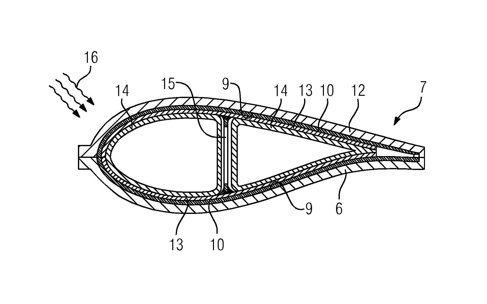
CROSS REFERENCE TO RELATED APPLICATIONS[0001]This application claims the benefit of European Application No. EP14158886 filed Mar. 11, 2014 incorporated by reference herein in its entirety.FIELD OF INVENTION[0002]The present invention relates to a method for manufacturing a component for a wind turbine, in particular a rotor blade.BACKGROUND OF INVENTION[0003]Modern wind turbine rotor blades are built from fiber-reinforced composites combined with core members, such as balsa wood or plastic foam.[0004]For example, EP 2 123 431 A1 describes a method for manufacturing a rotor blade using a vacuum-assisted resin transfer molding (VARTM)-process. In a first step of the manufacturing process, fiber material is laid onto a lower part and an upper part of a mold, respectively. The fiber material is secured in place by vacuum applied from beneath. Then, mold cores are covered in vacuum bags and are placed in the lower part of the mold together with a web (also known as a shear web). Next, t...

Claims


Application Information

Patent Timeline
IPC IPC(8): B32B43/00
CPCB32B43/006B29C70/48B29C70/54B29L2031/085B29K2631/04B29C33/58B29C33/68B29D99/0025B29C70/30Y10T156/1195Y02P70/50
Inventor BERNHARD, BENLYTANGAGER, KIM
Owner SIEMENS AG
Learn More