
Hand-Operated Tool Device With A Brake Mechanism For Braking A Machining Tool

Inactive Publication Date: 2015-09-17
HILTI AG
View PDF20 Cites 2 Cited by
  • Summary
  • Abstract
  • Description
  • Claims
  • Application Information

AI Technical Summary

Benefits of technology

[0010]Particularly preferably the brake band has a stop element, which can be moved between the first stopper and the second stopper. The stop element is positioned on the second end of the brake band, which is turned toward the tension spring. Due to the

Problems solved by technology

A disadvantage is that the blocking of the brake drum results in a pitching movement of the tool device.
The pitching movement is particularly problematic in hand-operated tool devices that have a machining tool with

Method used


Image

  • Hand-Operated Tool Device With A Brake Mechanism For Braking A Machining Tool
  • Hand-Operated Tool Device With A Brake Mechanism For Braking A Machining Tool
  • Hand-Operated Tool Device With A Brake Mechanism For Braking A Machining Tool

Examples


Example

DETAILED DESCRIPTION OF THE DRAWINGS

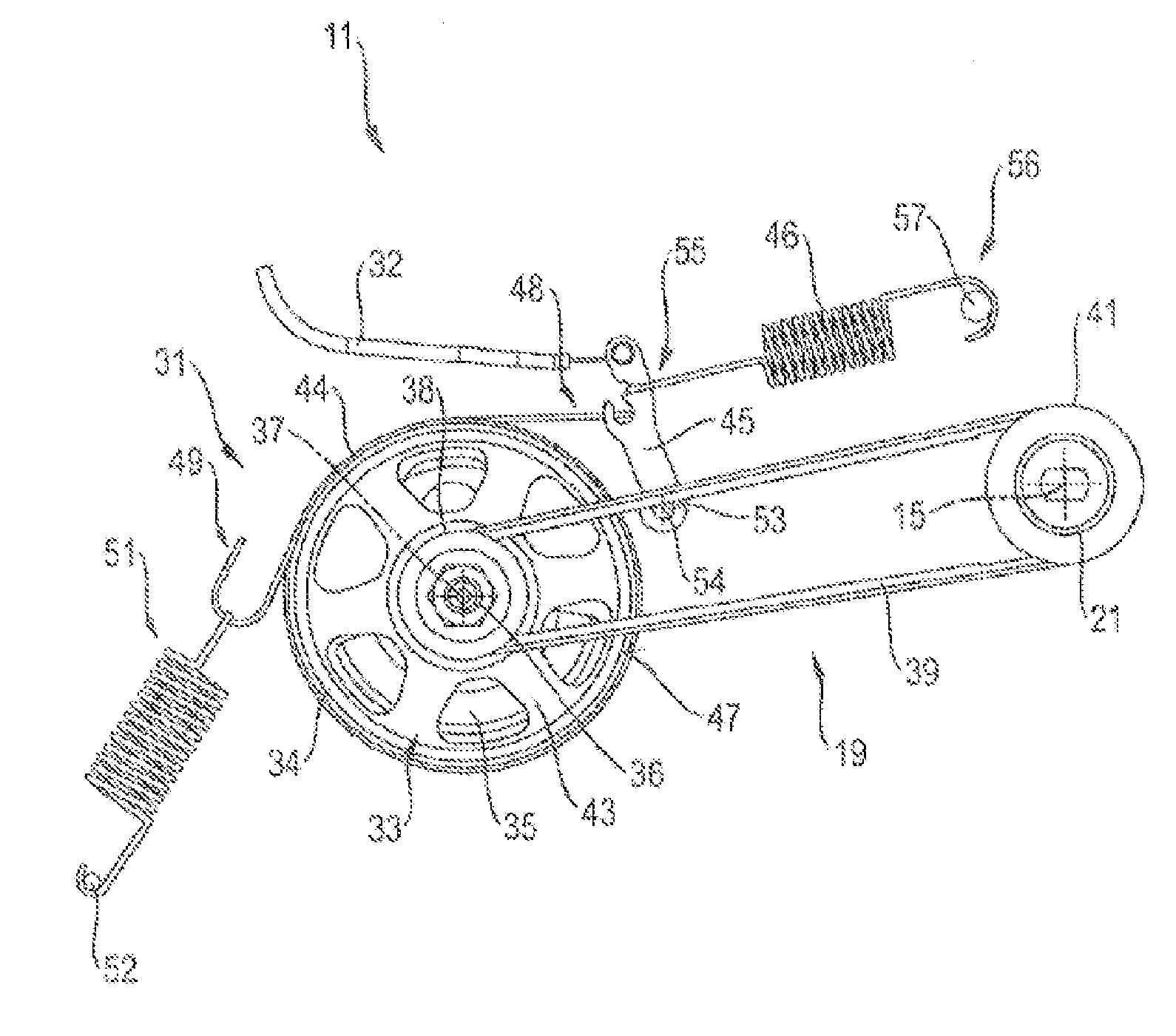
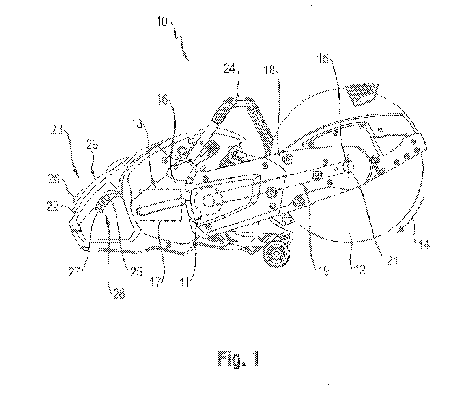
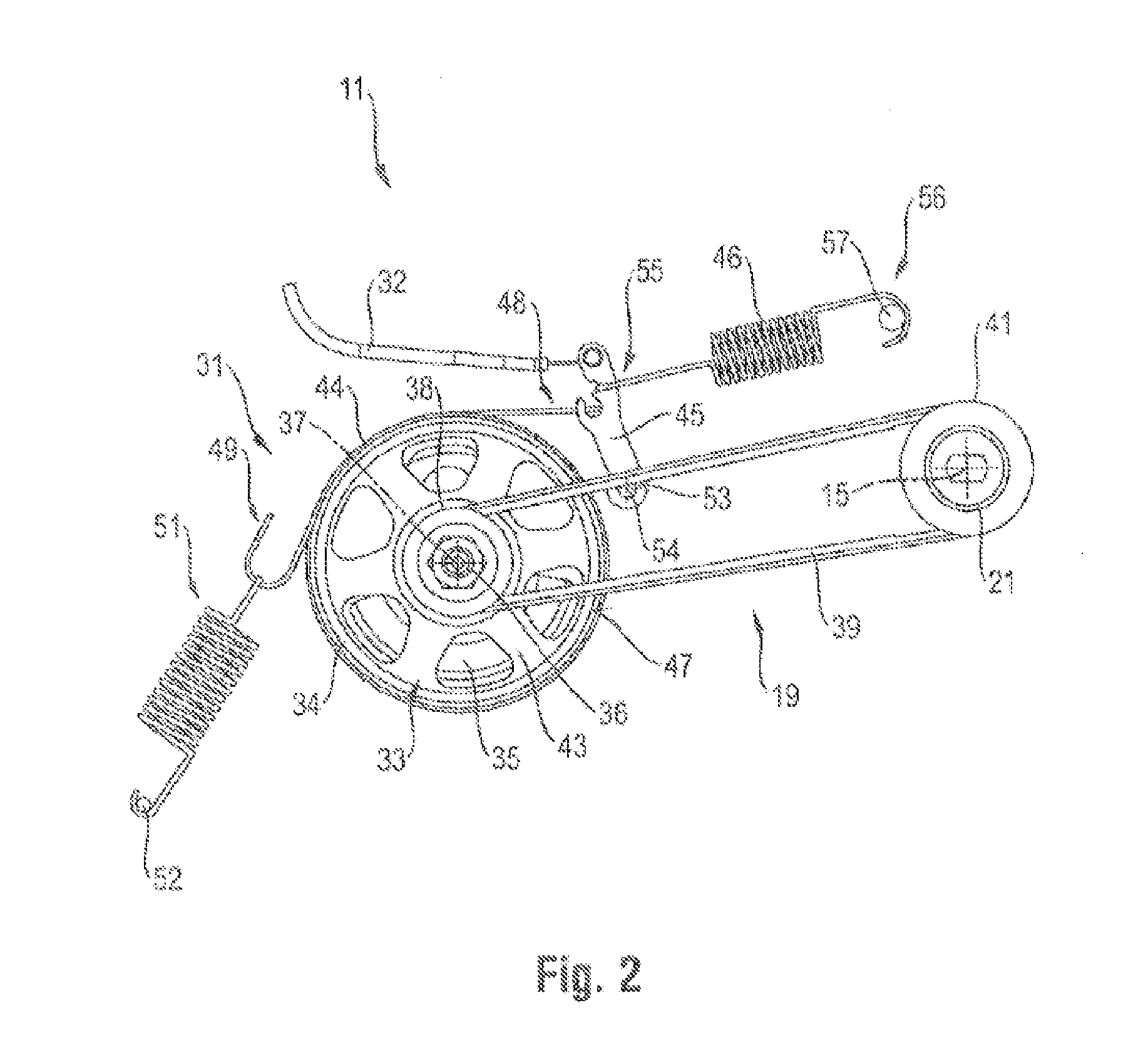
[0017]FIG. 1 shows a hand-operated tool device 10 according to the invention that is designed in the form of a cutoff grinder, with a brake mechanism 11 for braking a drive device in a three-dimensional representation.

[0018]The cutoff grinder 10 has a machining tool designed as a cutoff wheel 12, which is driven by a drive device 13 in a rotational direction 14 around an axis of rotation 15. Here all drive components for the cutoff wheel 12 are summarized under the term “drive device.” The drive device 13 of the cutoff grinder 10 shown in FIG. 1 comprises a drive motor 17 positioned in a motor housing 16, a belt drive 19 positioned in a supporting arm 18 and an output shaft 21, on which the cutoff wheel 12 is mounted. If necessary, additional transmission components can be connected between the drive motor 17 and the belt drive 19.

[0019]To operate the cutoff grinder 10, a first hand grip 22 is planned, which has a control device 23 and in the embo...


PUM


Abstract

A hand-operated tool device with a brake mechanism for braking a machining tool is disclosed. The tool device has a drive device, a band brake with a brake drum and a brake band that loops around the brake drum, and a control device with a brake switch for activating the band brake. A first end of the brake band is connected with the brake switch via a transmission device. A pivot-mounted brake lever is connected between the brake band and transmission device and the brake lever is pre-tensioned by a brake spring. A second end of the brake band is connected with a tension spring. The spring rigidity of the tension spring is greater than the spring rigidity of the brake spring.

Description

[0001]This application claims the priority of International Application No. PCT / EP2013 / 070420, filed Oct. 1, 2013, and German Patent Document No. 10 2012 218 072.9, filed Oct. 3, 2012, the disclosures of which are expressly incorporated by reference herein.BACKGROUND AND SUMMARY OF THE INVENTION[0002]The current invention refers to a hand-operated tool device with a brake mechanism for braking a machining tool.[0003]Under the term “tool device” in the context of the current invention all tool devices are summarized that drive a machining tool around an axis of rotation during the processing of a work piece. Typical examples of such tool devices are a cutoff grinder, an angle grinder, a circular saw, a chain saw and a core drill. Tool devices that are at least partially operated by hand by the user during the processing of a work piece are labeled hand operated. In addition to tool devices that are operated directly by the operator over the work piece, tool devices that are installed...

Claims


Application Information

Patent Timeline
IPC IPC(8): F16D49/10B27B5/38B27B17/08B24B47/26
CPCF16D49/10B27B17/083B27B5/38B24B47/26F16D2121/16F16D2125/20F16D2125/60F16D49/08
Inventor STEINGRUBER, ADRIAN
Owner HILTI AG
Learn More