Current sensor and method for manufacturing current sensor

a current sensor and current sensor technology, applied in the field of current sensors, can solve the problems of increased size of magnetic shield cores and greater influence, and achieve the effect of suppressing magnetic saturation and high-speed responsiveness

Active Publication Date: 2015-09-17
YAZAKI CORP
View PDF5 Cites 23 Cited by
  • Summary
  • Abstract
  • Description
  • Claims
  • Application Information

AI Technical Summary

Benefits of technology

[0013]The present invention was made in view of the above circumstances, and an object thereof is to provide a current sensor which achieves high-speed responsiveness without causing an increase

Problems solved by technology

However, the aforementioned countermeasure (1) has a problem in that the size of the magnetic shield core increases, and the aforementioned countermeasure (2)

Method used


Image

  • Current sensor and method for manufacturing current sensor
  • Current sensor and method for manufacturing current sensor
  • Current sensor and method for manufacturing current sensor

Examples


first embodiment

[0049]First, a description will be given of a current sensor according to a first embodiment.

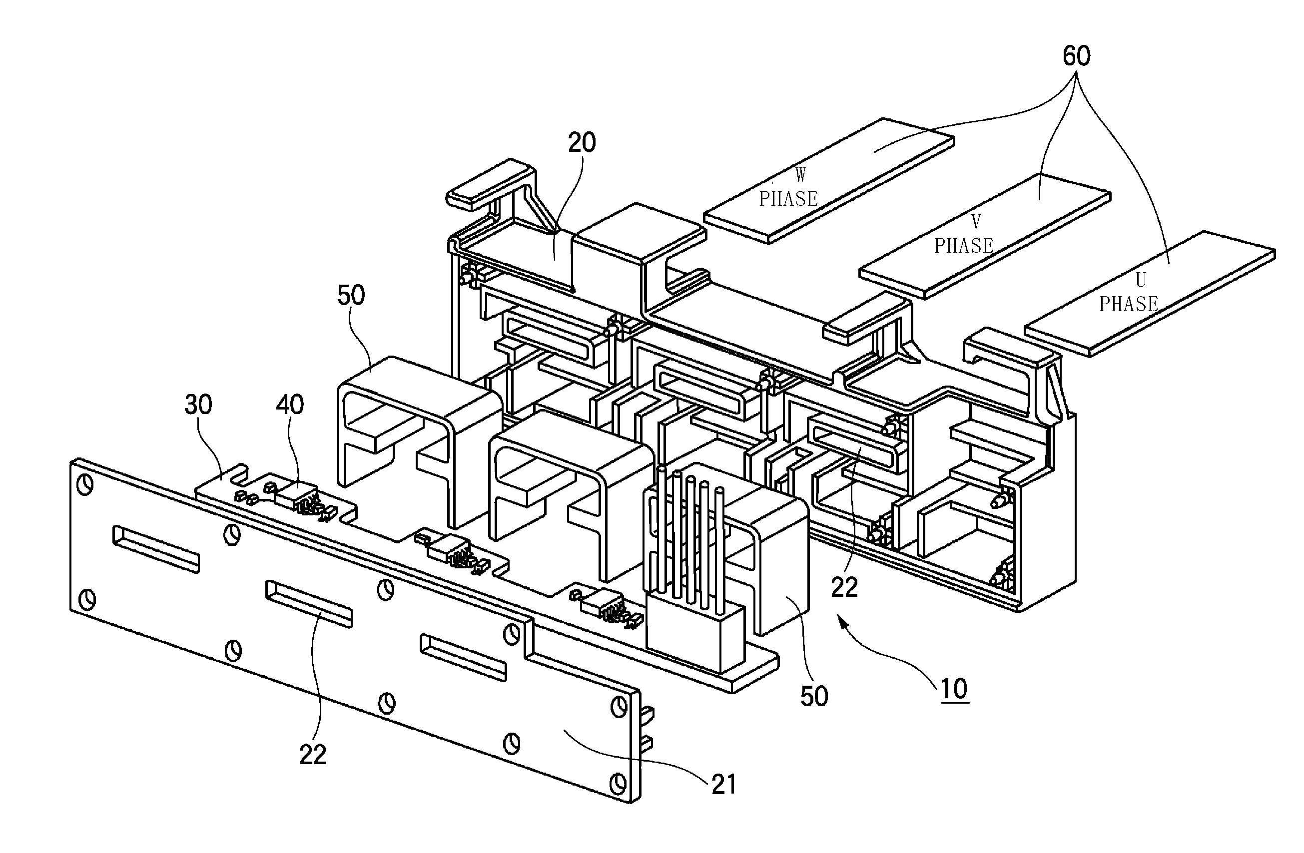
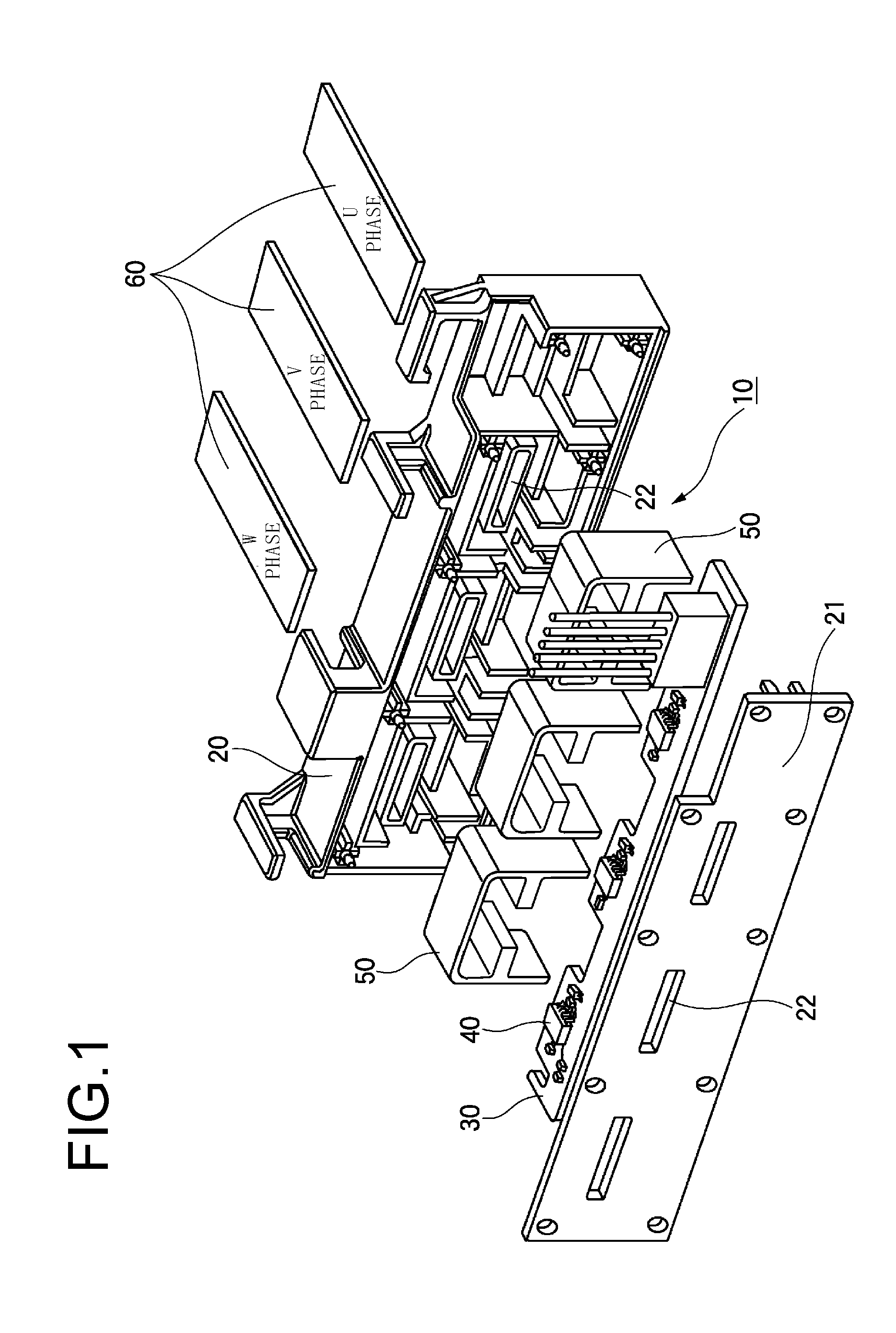
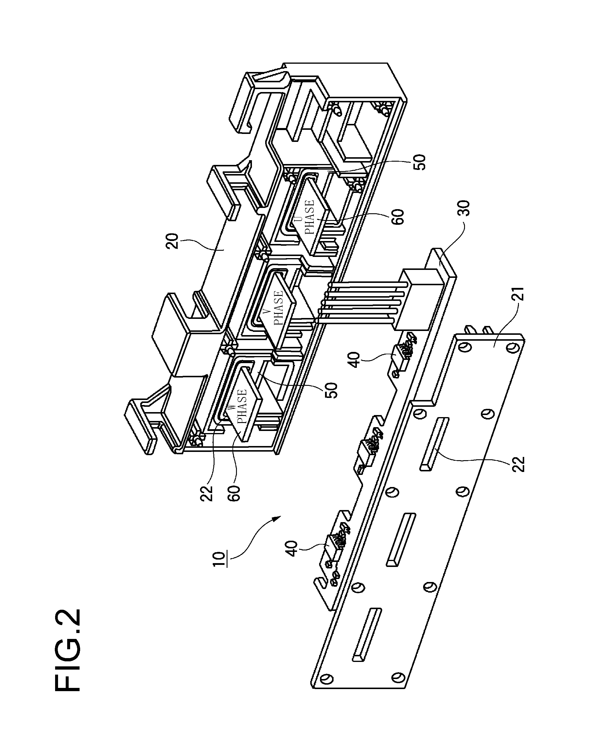
[0050]FIG. 1 is an exploded perspective view illustrating the current sensor according to the first embodiment, FIG. 2 is a perspective view of the current sensor in FIG. 1 in the course of assembly, FIG. 3 is a perspective view of a magnetic shield core in the current sensor according to the first embodiment, and FIG. 4 is a front view of the magnetic shield core in the current sensor according to the first embodiment.

[0051]As illustrated in FIGS. 1 and 2, the current sensor 10 is configured to include a housing 20, a substrate 30 accommodated in the housing 20, magnetic detection elements 40 mounted on the substrate 30, and magnetic shield cores 50 accommodated in the housing 20. According to the current sensor 10, current paths 60 are arranged between the magnetic detection elements 40 and the magnetic shield cores 50, and the magnetic detection elements 40 detect a current flowing throug...

second embodiment

[0074]Next, a description will be given of a current sensor according to a second embodiment, in which the same reference numerals are given to the same components as those in the first embodiment, and the descriptions thereof will be omitted.

[0075]As illustrated in FIG. 8, a magnetic shield core 50 which configures the current sensor 10 according to the second embodiment includes an inner shield 50a and an outer shield 50b.

[0076]The inner shield 50a is formed in a ring shape so as to extend around the current path 60. In addition, a gap portion 52 is formed in the inner shield 50a on the side of the magnetic detection element 40 by cutting a part of the inner shield 50a, and projecting portions 54 which are positioned on both sides of the gap portion 52 are formed.

[0077]The outer shield 50b is formed in a substantially U shape and is arranged along the outer circumference of the inner shield 50a. A part of the outer shield 50b along the outer circumference of the inner shield 50a ...


PUM


Abstract

A current sensor includes a magnetic detection element configured to detect magnetism produced from a current path and a magnetic shield core. The magnetic shield core includes a core portion arranged so as to extend around the current path such that the current path is positioned therein, a gap portion formed by cutting a part of the core portion and in which the magnetic detection element is arranged, and at least a pair of shield portions extending from the core portion toward the outside opposite to the inside of the core portion where the current path is arranged, so as to correspond to the magnetic detection element.

Description

CROSS REFERENCE TO RELATED APPLICATION[0001]This application is a continuation of PCT application No. PCT / JP2013 / 082438, which was filed on Dec. 3, 2013 based on Japanese Patent Application (No. 2012-264524) filed on Dec. 3, 2012, the contents of which are incorporated herein by reference. Also, all the references cited herein are incorporated as a whole.BACKGROUND[0002]1. Technical Field[0003]The present invention relates to a current sensor used for measuring a current flowing through a current path and a method for manufacturing the current sensor.[0004]2. Background Art[0005]In order to measure a current of a battery mounted on a vehicle or a current to be supplied to a motor, a current sensor which is provided with a magnetic detection element such as a hall element and a magnetic shield core, detects magnetism produced from a current path such as a bus bar, and measures a current flowing through a current path has been used (see JP-A-2010-223868, JP-A-2010-2277 and JP-B-451585...

Claims


Application Information

Patent Timeline
IPC IPC(8): G01R15/20G01R1/18
CPCG01R1/18G01R15/207G01R3/00
Inventor SAKAMOTO, AKINORIHASHIO, SHINICHIPENG, SHIDI
Owner YAZAKI CORP
Why Eureka
Try Eureka