Redundant Brushless Drive System

Active Publication Date: 2015-09-17
DR FRITZ FAULHABER
View PDF10 Cites 6 Cited by
  • Summary
  • Abstract
  • Description
  • Claims
  • Application Information

AI Technical Summary

Benefits of technology

The patent text describes a new inventive drive system for electric motors that uses a special arrangement of sensor groups to control the phases of the motor's coil. This design makes the coil extremely light and stable, and also allows for a redundant sensor system that requires little installation space. The sensor groups are arranged in a way that they can be associated with different phase windings, making it easy to control each motor's movement. Additionally, an integrated encoder chip can be used to further reduce installation space and make the sensor system even more space-saving and user-friendly. Overall, this invention reduces the size and complexity of electric motors while ensuring stability and efficiency.

Problems solved by technology

Such an electric motor has the disadvantage that a relatively large installation space is needed for arrangement of the magnetic pole pairs and the coils.
Such a direct-current motor requires a relatively large installation space.
This also has the disadvantage that upon the failure of a motor unit the motor power is relatively lower.
This would have the disadvantage that additional components would be needed for such a control unit.

Method used


Image

  • Redundant Brushless Drive System
  • Redundant Brushless Drive System
  • Redundant Brushless Drive System

Examples


Embodiment Construction

[0017]In the following description it is claimed that the invention is not limited to the exemplary embodiments and thereby not to all or a plurality of features of the described feature combinations; moreover, each individual partial feature of the / of each exemplary embodiment is also dissociated from all other partial features described in conjunction therewith and also in combination with any desired features of another exemplary embodiment of significance for the object of the invention.

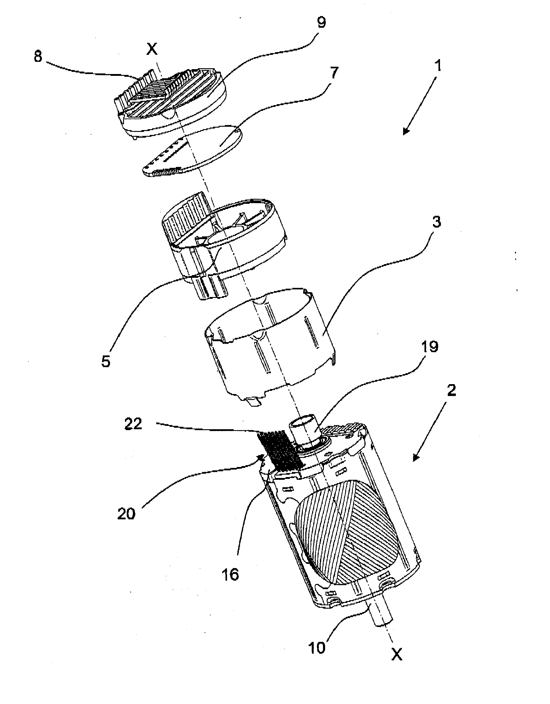
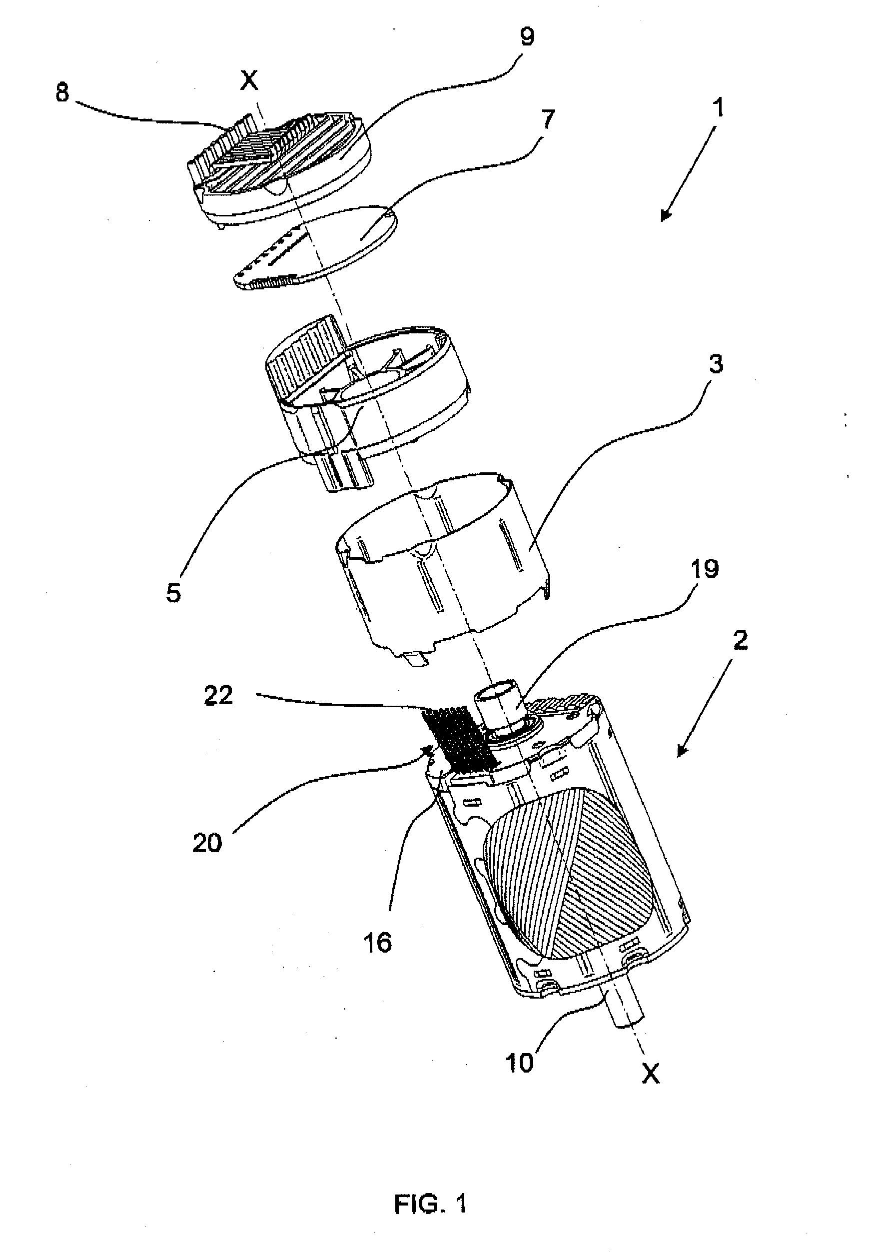
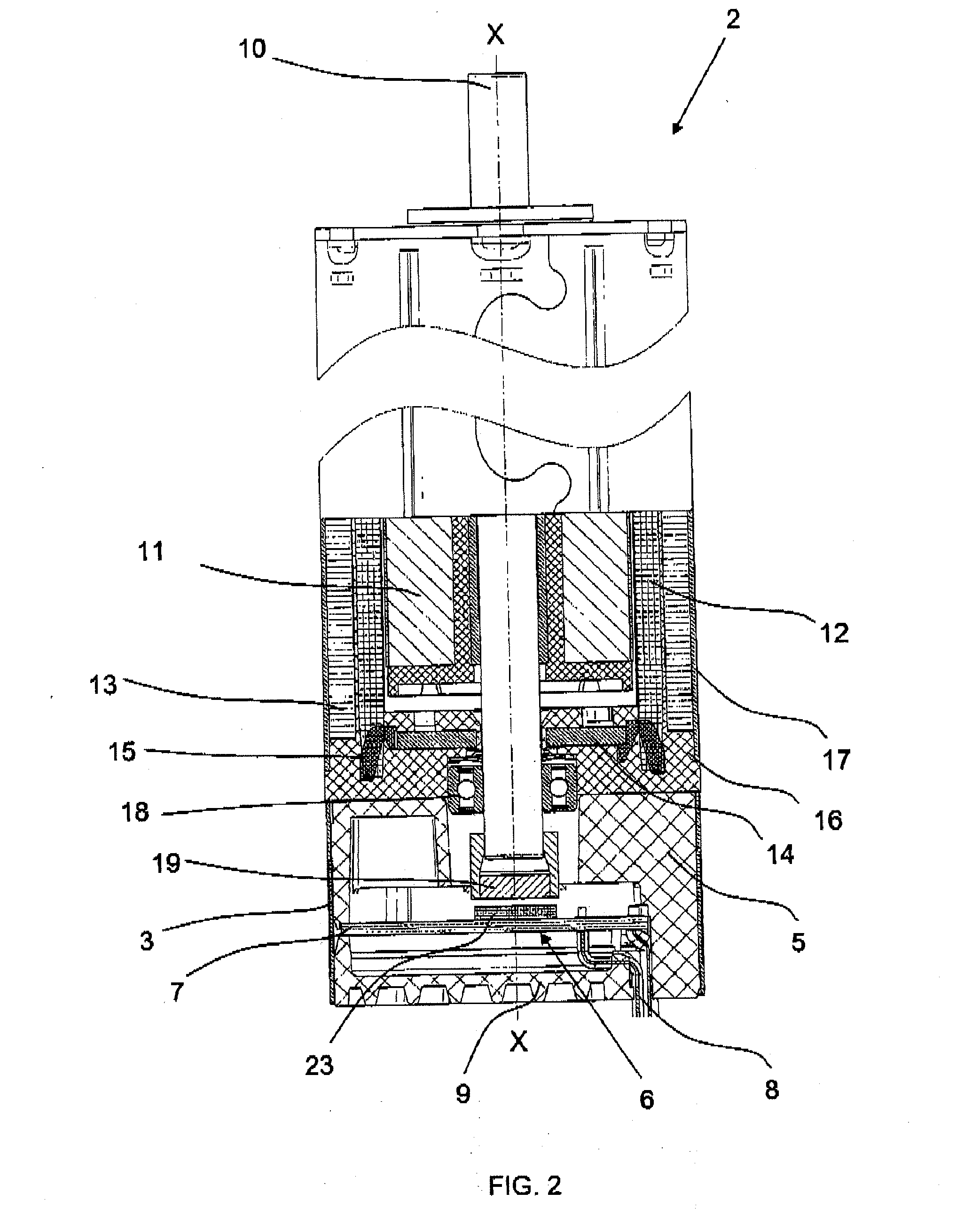
[0018]A preferred embodiment of an inventive brushless drive system 1 is depicted in FIG. 1 and FIG. 2. The drive system 1 includes in particular a motor unit 2, a housing 3, a flange 5, a sensor system 6, an encoder circuit board 7, drive system connections 8 provide motor connections and encoder connections, and a cover 9.

[0019]The motor unit 2 includes in particular a motor axle (shaft) 10, a rotor magnet 11 attached to the motor axle 10, a cylindrical coil 12, an iron counter plate 13 enclosi...


PUM


Abstract

A redundant brushless drive system, including a coil (12) having first and second phase windings operable independently of one another and first and second independently operable sensor groups for the rotational position of a rotor (11) and for commutation of the phase windings. The first and second sensor groups are positioned along the motor axle one-behind-the-other parallel to each other and symmetrical to the motor axle (10). An encoder circuit board (7) is configured such that an association of the sensor groups (G1, G2) to a phase winding (W1, W2) is configurable such that either the first sensor group (G1) is used for controlling the first phase winding (W1) and the second sensor group (G2) for controlling the second phase winding (W2), or the first sensor group (G1) is used for controlling the second phase winding (W2) and the second sensor group (G2) for controlling the first phase winding (W1).

Description

CROSS-REFERENCE TO RELATED APPLICATIONS[0001]This application claims priority to German Application No. 10 2014 103 607.7, filed Mar. 17, 2014.FIELD OF THE INVENTION[0002]The invention relates to a redundant brushless drive system, including a coil having a plurality of phase windings operable independently of one another and a sensor system including a plurality of independently operable sensor groups for acquiring the rotational position of a rotor and for commutation of the phase windings.BACKGROUND OF THE INVENTION[0003]Redundant brushless drive systems are used in particular in applications having heightened failure safety, for example in air travel, and are known in principle.[0004]A redundant electric motor is described in EP 0 754 365 B1. In the electric motor described by this reference the rotor includes two magnetic pole pairs disposed axially one-behind-the-other, wherein the stator in particular is formed from two separated coils correspondingly disposed axially one-beh...

Claims


Application Information

Patent Timeline
IPC IPC(8): H02K11/00H02K3/28H02K19/10
CPCH02K11/0021H02K11/0073H02K3/28H02K19/10H02K29/12H02K3/04H02K2213/06
Inventor WALLNER, HERBERTJADHAV, SANJAY
Owner DR FRITZ FAULHABER
Why Eureka
Try Eureka