Bearing power generating configuration

a technology of bearings and configurations, applied in the direction of bearings, mechanical energy handling, mechanical apparatus, etc., can solve the problems of mechanical failure, mechanical failure, wear to the various bearing components, and mechanical failure can affect the rotational motion and/or the axial linear restraint, so as to eliminate any wear and reliability problems and minimize impact

Inactive Publication Date: 2015-09-24
AB SKF
View PDF2 Cites 2 Cited by
  • Summary
  • Abstract
  • Description
  • Claims
  • Application Information

AI Technical Summary

Benefits of technology

[0026]One advantage of the present invention is the ability to generate a continued electrical current during motion of one of the rings of the bearing. The power can be utilized to operate bearing condition monitored equipment. The inclusion of an electrical power-generating device eliminates any need for a locally stored power (such as by a battery) or conveyed power from an external power source. By generating power at the location, the system can operate completely independent and un-tethered from any other device by providing sufficient power for wireless signal communications. While yet another advantage is that operation of the monitoring system can be limited to the time where the bearing is undergoing rotation. Power is only applied to the system when the generator is subjected to the relative motion between the bearing outer ring and the bearing inner ring.
[0027]Bearings can be utilized on equipment deployed in remote locations. The location could complicate any provisions for externally provided power for monitoring the condition of the bearing. The bearing(s) can be integrated into the equipment at a location that is difficult to access, particularly for wiring. Further, wires can accidentally interfere or become abraded by any rotational movements or other movements of components of the equipment.
[0028]Another advantage enables the registration between the electrical power generator and the magnetically polarized material to adapt to changes and wear of the bearing. The mechanical interface includes features to accommodate for radial and axial changes between the electrical power generator and the magnetically polarized material.
[0029]The use of a magnetic density operated generator core eliminates any wear and reliability issues associated with moving components. Any contacting surfaces can include bearings, friction reduced surfaces, and the like to minimize any impact resulting from relative motion between two moving components contacting one another.
[0030]These and other features, aspects, and advantages of the invention will be further understood and appreciated by those skilled in the art by reference to the following written specification, claims and appended drawings, which follow.

Problems solved by technology

Bearings undergo significant use, which causes wear to the various bearing components.
Over time, the wear on the bearing can result in mechanical failure.
Mechanical failure can impact the rotational motion and / or the axial linear restraint.
Failure to control either of these movements can cause catastrophic failure to the machinery relying upon the bearing.
Bearing reliability and predictive servicing can impact the operation and uptime of equipment.
Over time, the bearings wear.
Bearing failure during operation can cause significant damage to the equipment and possibly the surrounding area.
The bearing failure could even potentially cause injury or death to people should the right circumstances come occur.

Method used


Image

  • Bearing power generating configuration
  • Bearing power generating configuration
  • Bearing power generating configuration

Examples


Embodiment Construction

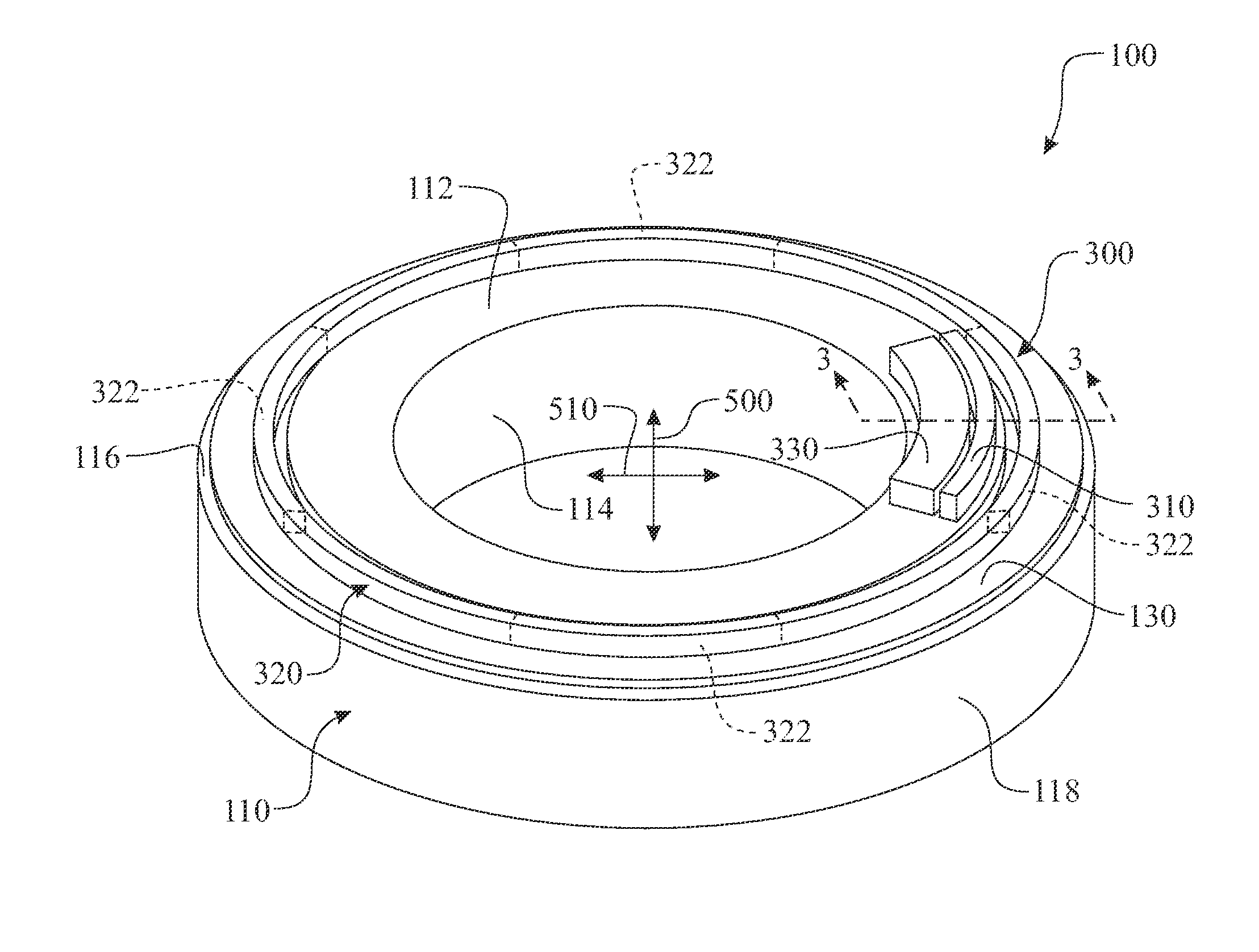
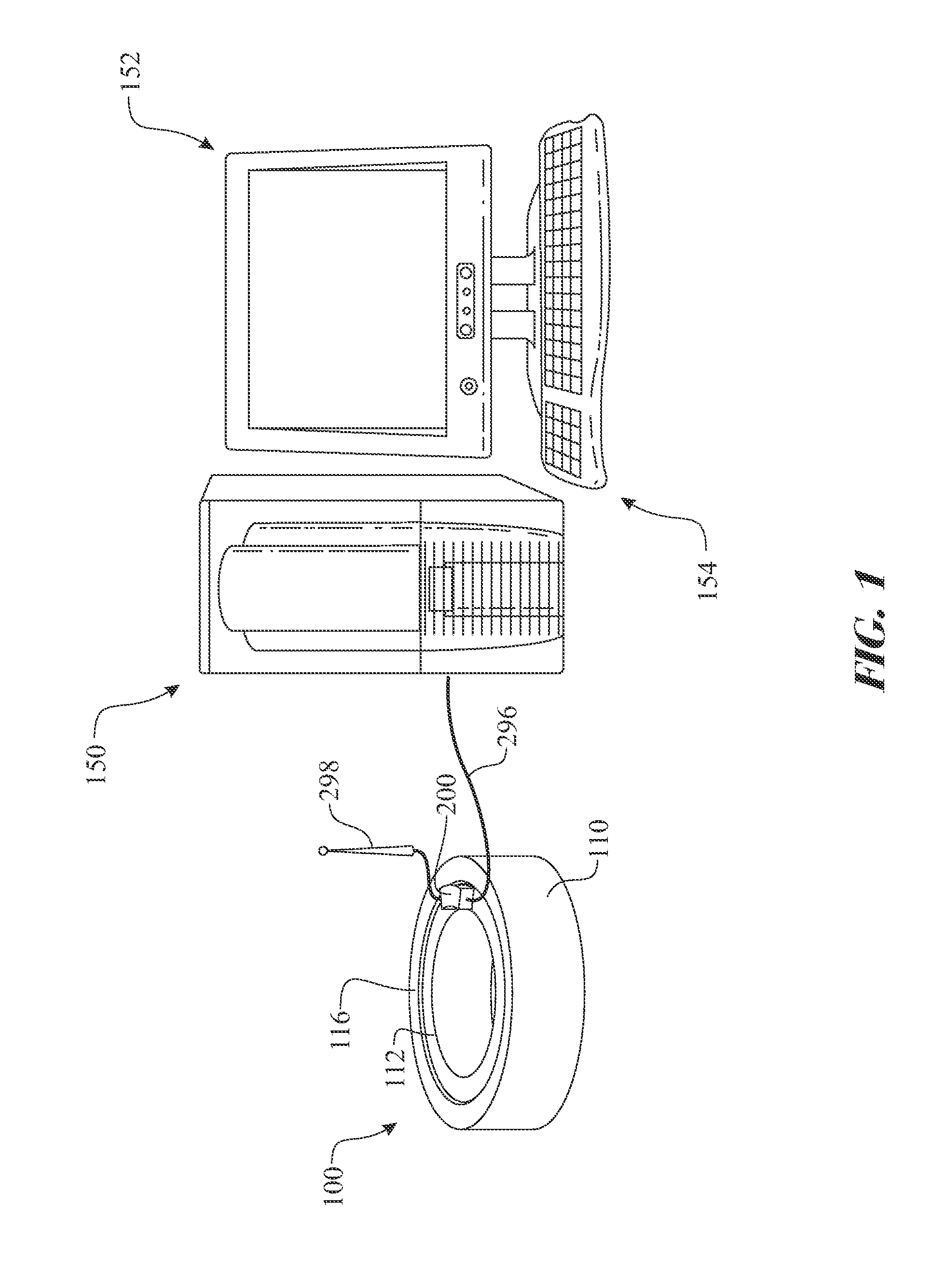
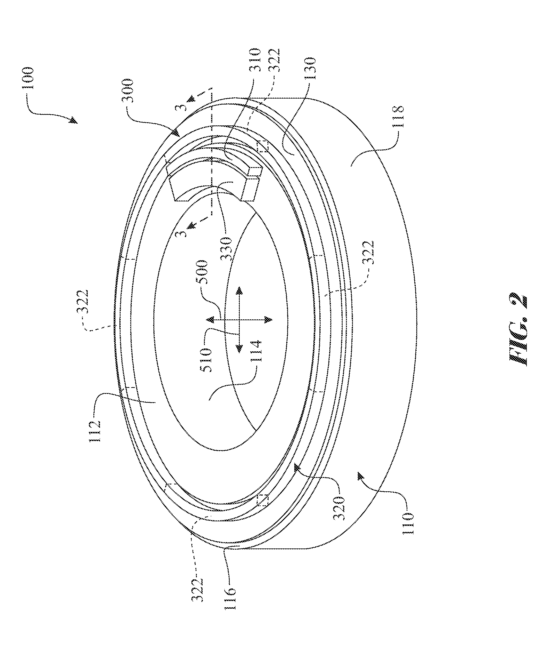
[0037]The following detailed description is merely exemplary in nature and is not intended to limit the described embodiments or the application and uses of the described embodiments. As used herein, the word “exemplary” or “illustrative” means “serving as an example, instance, or illustration.” Any implementation described herein as “exemplary” or “illustrative” is not necessarily to be construed as preferred or advantageous over other implementations. All of the implementations described below are exemplary implementations provided to enable persons skilled in the art to make or use the embodiments of the disclosure and are not intended to limit the scope of the disclosure, which is defined by the claims. For purposes of description herein, the terms “upper”, “lower”, “left”, “rear”, “right”, “front”, “vertical”, “horizontal”, and derivatives thereof shall relate to the invention as oriented in FIG. 1. Furthermore, there is no intention to be bound by any expressed or implied theo...


PUM


Abstract

A power generating bearing assembly comprising a power generating subassembly integrated into a bearing. The power generating subassembly utilizes the relative motion between a bearing inner ring and a bearing outer ring of the bearing to generate electrical power. A sealing system is attached to one of the bearings. The power generating subassembly includes an electrical generator in operational engagement with a magnetically polarized material. The electrical generator is attached to the non-sealing carrying bearing. The magnetically polarized material can be attached directly to the sealing system or carried by a magnetically polarized material mount ring. The relative motion between the rings engages the electrical generator and the magnetically polarized material causing a generator core of the electrical generator to create an electrical current.

Description

CROSS REFERENCE TO RELATED APPLICATIONS[0001]This is a National Stage application claiming the benefit of International Application Number PCT / EP2013 / 057381 filed on 09 Apr. 2013 (Sep. 4, 2013), which claims the benefit of International Application Number PCT / EP2012 / 057434 filed on 24 Apr. 2012 (24.04.2012), both of which are incorporated herein by reference in their entireties.TECHNICAL FIELD OF THE INVENTION[0002]The present invention relates to an apparatus and method for generating power during motion of a bearing.BACKGROUND[0003]A bearing can be defined as any of various machine elements that constrain the relative motion between two or more parts to only the desired type of motion. This is typically to allow and promote free rotation about a longitudinal axis and / or restrain any linear movement of a component in a normal direction respective to the bearing. Bearings may be classified broadly according to the motions they allow and according to their principle of operation, as ...

Claims


Application Information

Patent Timeline
Patent Type & Authority Applications(United States)
IPC IPC(8): F16C41/00H02K7/18F16C33/72
CPCF16C41/004H02K7/183F16C33/72H02K7/1846
Inventor BARTL, FRANKERSKINE, JOSEPHZIEGLER, SEBASTIANVAN DER HAM, ANDREAS CLEMENS
Owner AB SKF
Why Eureka
Try Eureka