

Multiple disc clutch device for vehicle
a multi-disc clutch and vehicle technology, applied in the direction of mechanical actuated clutches, interlocking clutches, transportation and packaging, etc., can solve the problems of insufficient durability insufficient drag torque of the multiple-disc clutch device, and large torque of the multiple-disc clutch device. , to achieve the effect of improving fuel economy, reducing the drag torque of the multiple-disc clutch device, and improving fuel efficiency
- Summary
- Abstract
- Description
- Claims
- Application Information
AI Technical Summary
Benefits of technology
Problems solved by technology
Method used
Image

Examples
Embodiment Construction
[0022]Hereinafter, an embodiment of the invention will be described in detail with reference to the accompanying drawings. In the following embodiment, the drawings are modified or simplified where appropriate, and the scale ratio, shape, and the like, of each portion are not always drawn accurately.
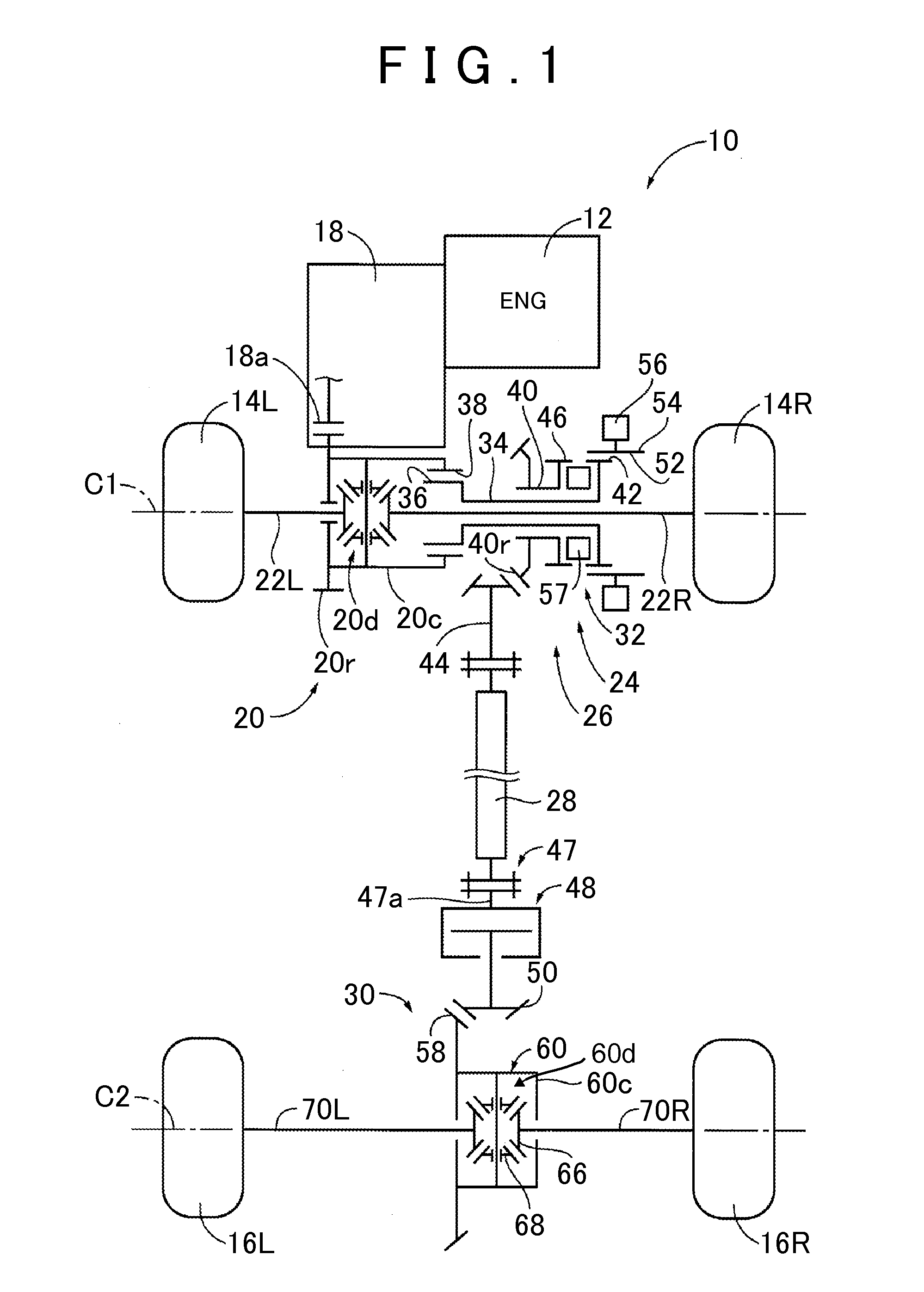
[0023]FIG. 1 is a skeletal view that schematically illustrates the configuration of a four-wheel drive vehicle 10 to which the invention is suitably applied. As shown in FIG. 1, the four-wheel drive vehicle 10 uses an engine 12 as a driving source, and includes an FF-base four-wheel drive system including a first power transmission path and a second power transmission path. The first power transmission path transmits power from the engine 12 to right and left front wheels 14R, 14L corresponding to main drive wheels. The second power transmission path transmits power from the engine 12 to right and left rear wheels 16R, 16L corresponding to auxiliary drive wheels. In a two-wheel drive mod...
PUM
 Abstract
Description
Claims
Application Information