Topology and control strategy for hybrid storage systems

Inactive Publication Date: 2015-09-24
ROBERT BOSCH SEA PTE
View PDF11 Cites 35 Cited by
  • Summary
  • Abstract
  • Description
  • Claims
  • Application Information

AI Technical Summary

Problems solved by technology

However, over the total lifetime of a RES, the Pb battery often becomes the main cost driver since it has to be changed every 1 to 3 years resulting in high costs for ac

Method used


Image

  • Topology and control strategy for hybrid storage systems
  • Topology and control strategy for hybrid storage systems
  • Topology and control strategy for hybrid storage systems

Examples


Embodiment Construction

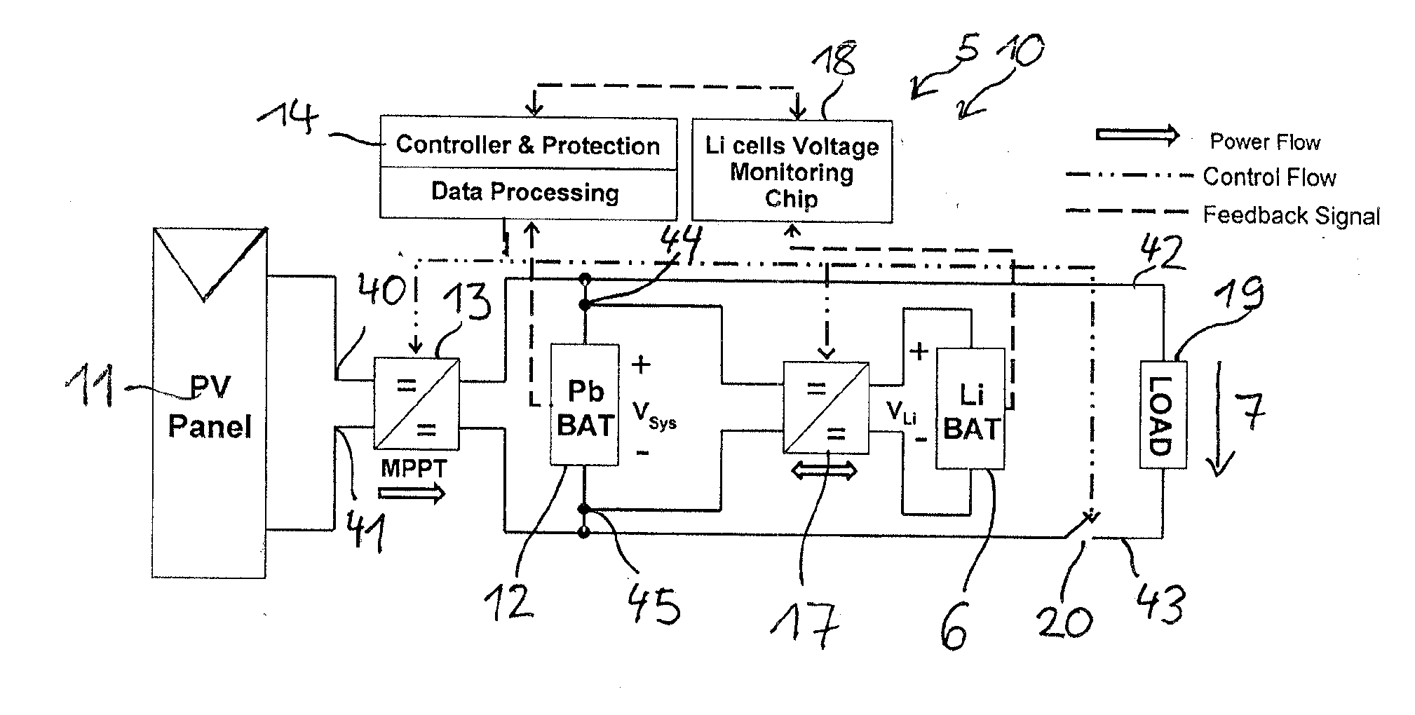
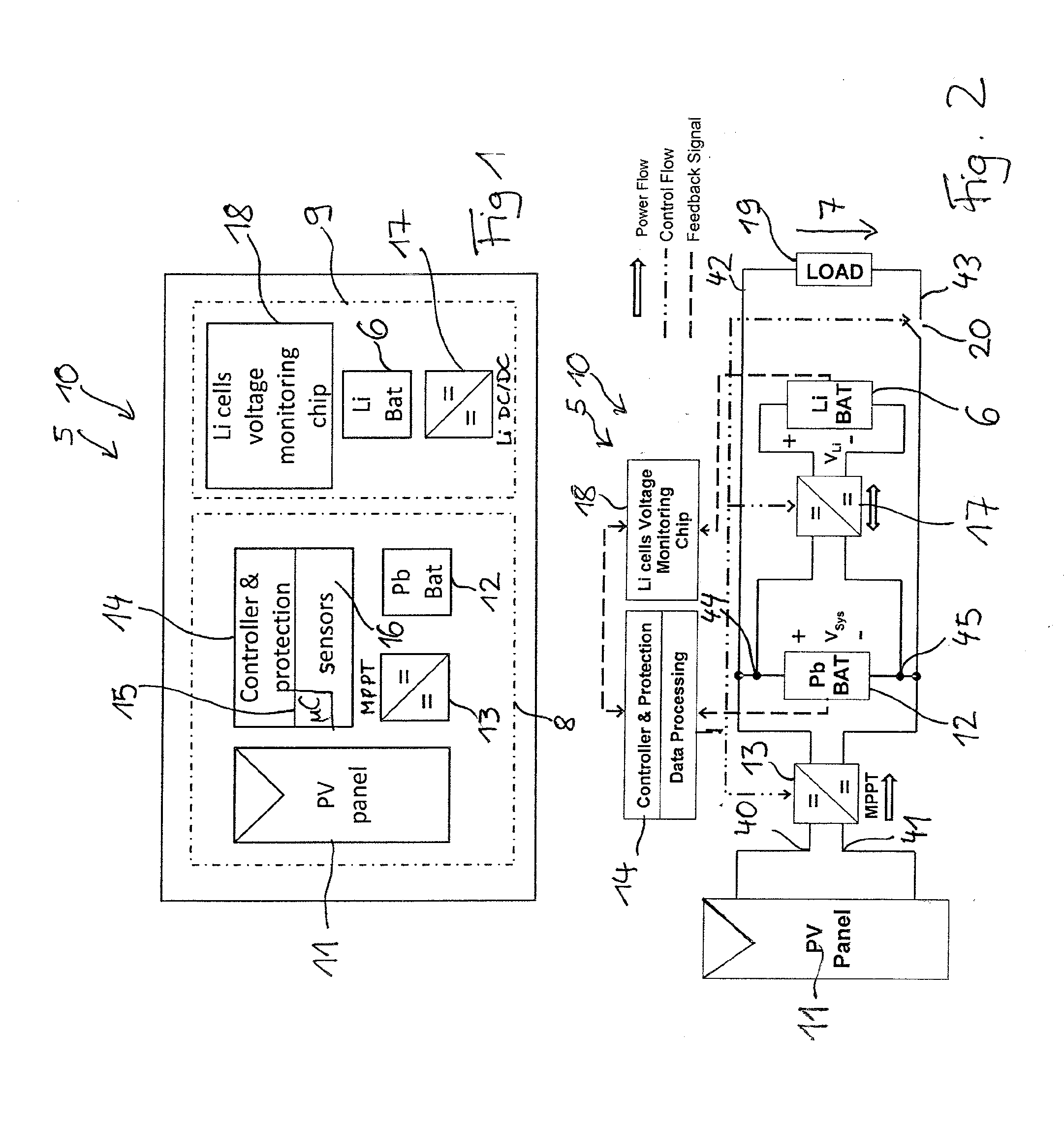
[0049]FIG. 1 shows a general layout of a hybrid storage system 5 with a hybrid battery charging device 10 according to the application. According to the application, a hybrid storage system comprises at least one battery while a hybrid charging device does not necessarily include the batteries.

[0050]The hybrid storage system 5 comprises a photovoltaic panel 11, a first energy storage subsystem 8 and a second energy storage subsystem 9. The first energy storage subsystem 8 comprises a lead battery 12, a unidirectional DC / DC converter 13 and a charge control system 14. The charge control system 14 comprises a microcontroller 15 and sensors 16. The sensors 16 comprise a voltage sensor at the terminals of the lead-acid battery. The DC / DC converter 13 is connected to a maximum power point tracker (MPPT). The maximum power point tracker provides an impedance matching for the photovoltaic panel 11 and it may be realized by a portion of the charge control system 14 and further hardware comp...


PUM


Abstract

A hybrid battery charging device includes: input terminals for connecting a photovoltaic panel or other current sources; first battery connections for connecting a lead-acid battery; second battery for connecting a high-cycle chemical battery; a two-way DC/DC converter having a first set of terminals connected with the second battery connections, and a second set of terminals connected with the first battery connections, an input of the second set of terminals being derived from the input terminals; a charge-and-discharge control system which is connected to the DC/DC converter via respective control lines; and output terminals for connecting a load, an input to the output terminals being derived from the first battery connections.

Description

BACKGROUND OF THE INVENTION[0001]1. Field of the Invention[0002]The present invention relates to a hybrid storage system for a re-mote energy system (RES).[0003]2. Description of the Related Art[0004]Lead acid batteries have been used for years as the main storage medium in off-grid solar systems and in remote energy systems (RES) in general. The popularity of lead acid batteries is mainly motivated by their low purchasing price. However, over the total lifetime of a RES, the Pb battery often becomes the main cost driver since it has to be changed every 1 to 3 years resulting in high costs for acquiring and changing several batteries. This relatively short lifetime, compared, for example, to lead (Pb) batteries in back-up systems, is due to the nature of remote energy applications. For example, in an off-grid solar system a battery is partly charged during daytime for several hours depending on the geographic location and on the weather and mainly discharged during night time, for e...

Claims


Application Information

Patent Timeline
IPC IPC(8): H02J7/00H02J7/35
CPCH02J7/35H02J7/0052H01M16/00H02J7/0013H02J7/0049H02J7/0048H02J2300/26H02J3/381H02J7/00047Y02E10/56H02J3/46H02J7/00
Inventor ADELMANN, PETERWOLST, OLIVERHE, MAO JUNHAMADA, MAHMOUDSENGEBUSCH, FALCOLI, YANLINKUFNER, ANNIKA
Owner ROBERT BOSCH SEA PTE
Why Eureka
Try Eureka