

Gas separation system and enriched gas production method
a gas separation system and gas production method technology, applied in the direction of separation process, dispersed particle separation, chemistry apparatus and processes, etc., can solve the problem of low permeability, achieve the effect of reducing the membrane area in the entire system, reducing the number of membrane modules, and reducing initial cos
Inactive Publication Date: 2015-10-01
UBE IND LTD
View PDF5 Cites 7 Cited by
- Summary
- Abstract
- Description
- Claims
- Application Information
AI Technical Summary
Benefits of technology
The present invention allows for a reduction in the cost of a gas separation system by decreasing the size of the membrane area and the number of membrane modules needed. This also maintains a high level of target gas recovery. In simple terms, the invention is a more cost-effective gas separation system.
Problems solved by technology
In this case, however, the permeability is low, and thus, it is necessary to increase the membrane area or increase operation pressure.
Method used
View moreImage
Smart ImageViewing Examples

Examples
examples
[0065]The present invention is described in further detail below according to Examples thereof. The scope of the present invention, however, is not limited to these Examples.
Login to View More PUM
 Abstract
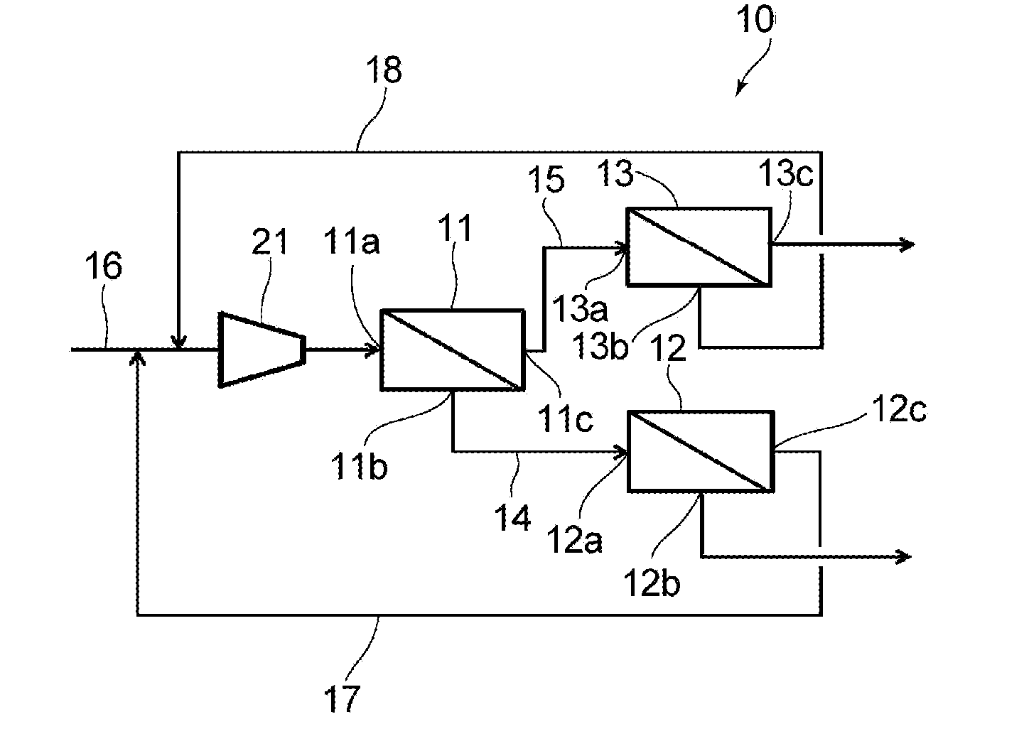
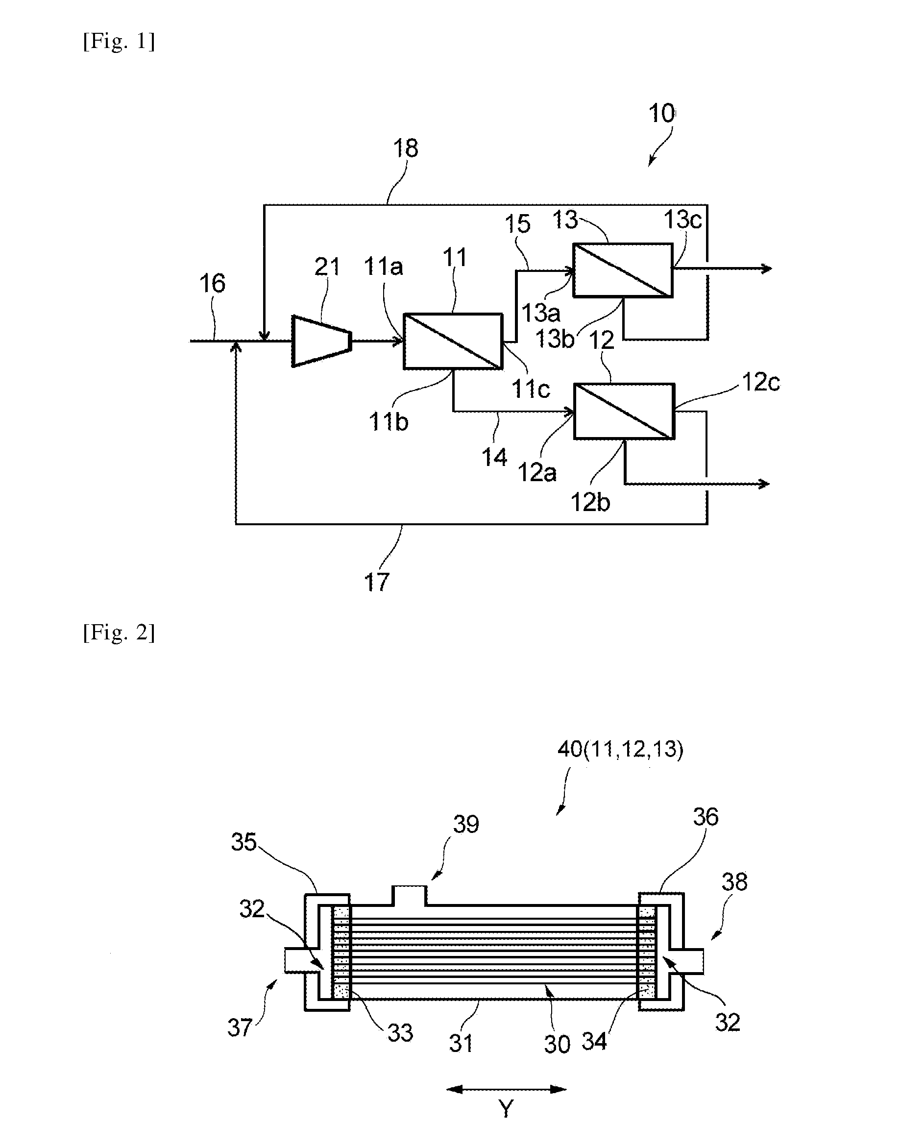
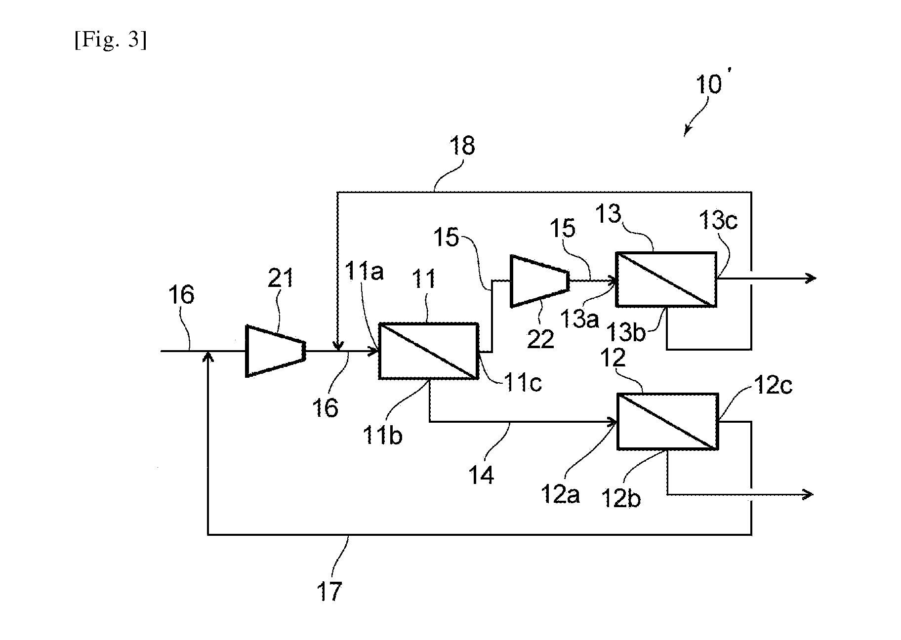
In a gas separation system, a retentate gas discharge port of a first unit U1 and a gas inlet port of a second unit U2 are connected by a retentate gas discharge line. A permeate gas discharge port of U1 and a gas inlet port of a third unit U3 are connected by a permeate gas discharge line. A feed gas mixture supply line is connected to a gas inlet port of U1. A permeate gas discharge port of U2 and the feed gas mixture supply line are connected by a permeate gas return line. A retentate gas discharge port of U3 and the feed gas mixture supply line are connected by a retentate gas return line. At least in operation, the gas permeability of U2 is higher than that of U3, and the gas selectivity of U3 is higher than that of U2.
Description
TECHNICAL FIELD[0001]The present invention relates to a gas separation system that separates a gas mixture by using a plurality of gas separation membrane units, and an enriched gas production method using this gas separation system.BACKGROUND ART[0002]The membrane separation method, which employs the difference in gas permeability with respect to a membrane, is known as a method for separating a gas mixture including at least two different gas species into the respective gases. With this method, at least either a highly-pure high-permeability gas or a highly-pure low-permeability gas, which are the target gases, can be obtained by recovering the permeate gas and / or the retentate gas. The permeability—which is the volume of permeation, through a membrane, of each gas included in the gas mixture per unit membrane area, per unit time, per unit partial pressure difference—can be expressed as P′ (unit: ×10−5 cm3 (STP) / cm2·sec·cmHg). The gas selectivity of the membrane can be expressed a...
Claims
Login to View More Application Information
Patent Timeline
 Patent Type & AuthorityApplications(United States)
IPC IPC(8): B01D53/22
CPCB01D2053/221B01D53/226
InventorFUKUDA, NOBUHIKONAKAMURA, TOMOHIDE
OwnerUBE IND LTD