Bipolar membrane device for producing gluconic acid

A gluconic acid and bipolar membrane technology, applied in the field of mechanical devices, can solve the problems of low operating current density, low operating efficiency, and high gluconic acid loss, and achieve the effects of uniform current distribution, reduced voltage loss, and reduced investment costs.

Active Publication Date: 2012-04-04
HANGZHOU WATER TREATMENT TECH DEV CENT
View PDF1 Cites 0 Cited by
  • Summary
  • Abstract
  • Description
  • Claims
  • Application Information

AI Technical Summary

Problems solved by technology

At present, if the bipolar membrane device used in domestic laboratory tests is directly enlarged, there will be: 1. The operating current density is too small, generally not greater than 400A / m 2 , it is impossible to use high current to operate, so that the membrane area of ​​the device with the same processing capacity is too large; 2. The solutions in the material liquid chamber and the sodium hydroxide chamber leak through each other, resulting in too low current efficiency, low conversion rate of grape acid products, and low hydrogen oxidation. The concentration of the sodium solution is too low, the energy consumption is too large and other shortcomings; 3. It is difficult for the suitable hydroxide to pass through the homogeneous positive membrane, so that the concentration of the sodium hydroxide solution cannot be increased, and the sodium hydroxide can pass through the positive membrane and The re-neutralization of the generated gluconic acid makes the operation efficiency low; 4. The separators selected are only suitable for heterogeneous membranes, and are directly used in bipolar membrane devices, which will cause internal leakage and external leakage; 5. The loss of gluconic acid is too high, and the gluconate radicals Will permeate the bipolar membrane or anodic membrane to the sodium hydroxide chamber, resulting in the loss of gluconic acid

Method used


Image

  • Bipolar membrane device for producing gluconic acid
  • Bipolar membrane device for producing gluconic acid
  • Bipolar membrane device for producing gluconic acid

Examples


Embodiment 1

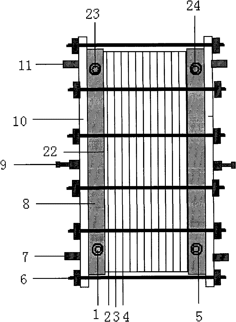
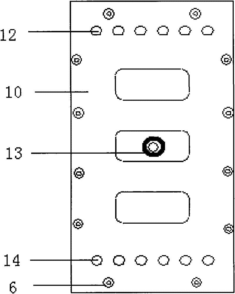
[0037] according to figure 2 , image 3 , Figure 4 , Figure 5 As shown in the structure, a bipolar membrane device is installed, including a clamping steel plate 10, an anode liquid channel plate 8, an electrode 22, an elastic separator 3, a homogeneous anodic membrane 2, a bipolar membrane 4, a fastening bolt 6, Feed liquid inlet 7, anode liquid flow channel plate 8, anode terminal 9, cathode terminal 13, elliptical liquid guide hole 17, net core separator 18, cathode terminal 13 is connected to cathode, anode terminal 9 is connected to anode ; A membrane stack space is formed between the cathode and the anode; the membrane group is placed in the membrane stack space, and the membrane group is placed as follows: homogeneous positive membrane 2, elastic separator 3, bipolar membrane 4, elastic separator 3, homogeneous The positive and negative membranes 2 are arranged in sequence; a net center spacer 18 is placed between the diaphragms; a semi-elliptical liquid guide hol...

Embodiment 2

[0041] Adopt the device in embodiment 1, wherein elastic coating 19 is polyurethane rubber type, adopts the film of 400*800 specification, altogether 150 groups, effective film area is 37.5 square, and electrode 22 is electroplated 1 micron thick on the 2 millimeter thick titanium alloy substrate The platinum layer adopts domestic bipolar membrane, the positive membrane adopts CSO membrane, the thickness of the separator is 0.7mm, and 3 groups of liquid guide holes are arranged side by side. Each liquid guide hole has 8 flow channels with a flow channel width of 0.2mm. The concentration of sodium feed solution is 30%, the concentration of sodium hydroxide chamber is 10%, and the current density is 600A / cm 2 Constant flow operation, membrane surface flow velocity 8cm / s, feed pressure 0.06MPa, pipe flow velocity 1.0m / s, liquid guide hole flow velocity 0.5m / s, membrane stack locking torque 45 N.m, continuous operation for 50 Hour. In the process of operation, except that the tem...

Embodiment 3

[0043] Using the device in Example 1, the elastic separator 3 is coated with an elastic coating 19 with a mass ratio of 2:1:0.5 of silicone rubber type: liquid polysulfide rubber type: flexible PVC elastic blend. 550*1100 membranes are used, 50 groups in total, the effective membrane area is 25 square meters, the electrode 22 is a 2 mm thick platinum plate, the domestic bipolar membrane is used, the positive membrane is HSF membrane, the thickness of the separator is 0.7mm, and the liquid guide holes are arranged side by side. 4 groups, the flow channel of each guide hole is 8 channels, the flow channel width is 0.2mm, the concentration of sodium gluconate feed solution is 30%, the concentration of sodium hydroxide chamber is 10%, and the current density is 600A / cm 2 Constant flow operation, membrane surface velocity 9cm / s, feed pressure 0.07MPa, pipe flow velocity 1.0m / s, liquid guide hole velocity 0.5m / s, membrane stack locking torque 35 N.m, continuous operation for 50 Hour...


PUM

PropertyMeasurementUnit
diameteraaaaaaaaaa
diameteraaaaaaaaaa
current efficiencyaaaaaaaaaa

Abstract

The invention discloses a mechanical device, and in particular relates to a device for producing gluconic acid. The device comprises a clamping steel plate, a polar liquid flow channel plate, a platinum electrode, a bipolar membrane, an elastic partition plate, a hydroxyl difficult penetrating homogeneous phase cationic membrane, and the like, wherein the electrode adopts a titanium alloy or platinum electrode with higher efficiency; an elastic coating is coated on the elastic partition plate for sealing; a material liquid inlet, a material liquid outlet, a sodium hydroxide liquid outlet and a sodium hydroxide inlet are arranged on the clamping steel plate, which is beneficial to the safety in the transportation process; and a liquid guide hole is improved and adopts an elliptic liquid guide hole. The invention has the advantages of high yield, no pollution, low running cost, convenience for transportation, and the like and can be widely applied to a glucose producing enterprise.

Description

technical field [0001] The invention relates to a mechanical device, in particular to a device for producing gluconic acid. technical background [0002] Gluconic acid derivatives are substances obtained from gluconic acid through a certain chemical reaction. Gluconic acid derivatives such as zinc gluconate, ferrous gluconate, copper gluconate, glucono-δ-lactone, etc. are a class of valuable products that are completely harmless to the human body, effective, safe and necessary food additives and nutritional supplements. The main products of its derivatives have been widely used in industrial fields such as medicine, food, chemical industry and construction. [0003] In the past 20 years, the development and application of gluconic acid derivatives in my country has achieved remarkable results. The development of products is getting faster and faster, and a large number of products have gone abroad. At present, domestic gluconic acid derivatives have developed from a relat...

Claims


Application Information

Patent Timeline
Patent Type & Authority Patents(China)
IPC IPC(8): C25B3/00C25B13/02
Inventor 金可勇金水玉高从堦
Owner HANGZHOU WATER TREATMENT TECH DEV CENT
Why Eureka
Try Eureka