Plasma system with integrated power supply, motion control, gas control and torch

a technology of motion control and plasma, applied in the field of cutting, can solve the problems of increasing system cost, installation time and complexity, and significant limitations in system performance, and achieve the effects of reducing the number of separate components needed, improving system level process control, and increasing user flexibility

Active Publication Date: 2015-10-01
LINCOLN GLOBAL INC
View PDF7 Cites 7 Cited by
  • Summary
  • Abstract
  • Description
  • Claims
  • Application Information

AI Technical Summary

Benefits of technology

[0005]An exemplary embodiment of the present invention is complete, integrated plasma cutting system having each of the plasma cutting power supply, motion and process controller, torch height control, gas control and user interface integrated into a single unit. The system will use a centralized microprocessor architecture which will control and sequence the plasma arc, regulate the gases and gas flows (rates and pressures), provide coordinated motion control of multiple axes along with controlling multiple height control system for plasma torches. In other exemplary embodiments, the user interface can be positioned remote from the remainder of the components to provide added user flexibility. Such a system will provide for improved system level process control, and the centralized microprocessor architecture will allow for packaging all of the system components within a single enclosure. This will minimize the number of separate components needed and optimize system performance, while at the same time increasing system reliability. Additionally embodiments of the present invention will minimize the number of interconnect cables and improve the overall system performance.

Problems solved by technology

This decentralized approach increases the system cost and installation time and complexity.
Additionally, the interconnects between the components of such a system can also lead to significant limitations in system performance.

Method used


Image

  • Plasma system with integrated power supply, motion control, gas control and torch
  • Plasma system with integrated power supply, motion control, gas control and torch
  • Plasma system with integrated power supply, motion control, gas control and torch

Examples


Embodiment Construction

[0010]Exemplary embodiments of the invention will now be described below by reference to the attached Figures. The described exemplary embodiments are intended to assist the understanding of the invention, and are not intended to limit the scope of the invention in any way. Like reference numerals refer to like elements throughout.

[0011]Embodiments of the present invention can be used for cutting various shapes and cutouts in many different materials, and is not limited to any particular cutting processes.

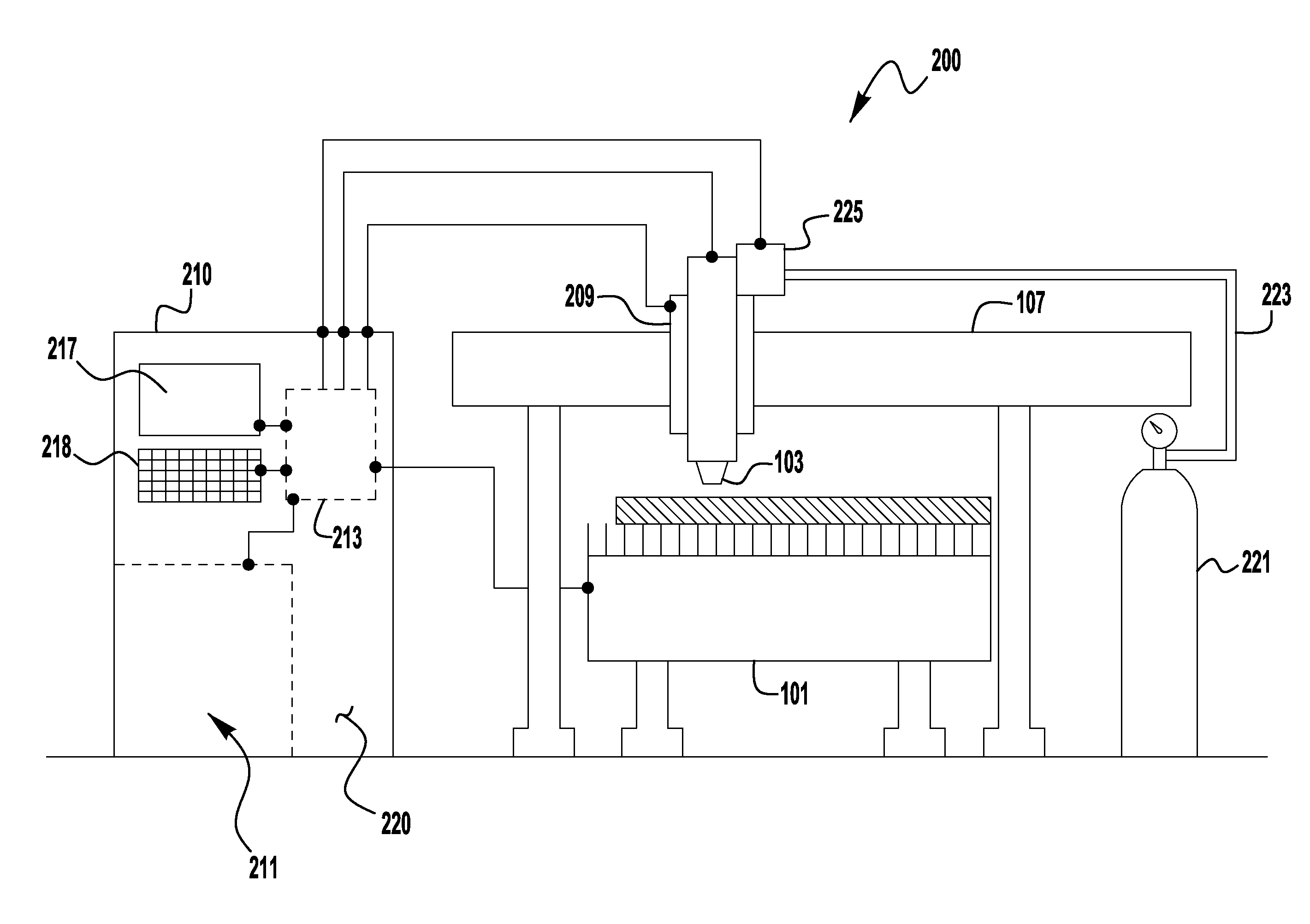
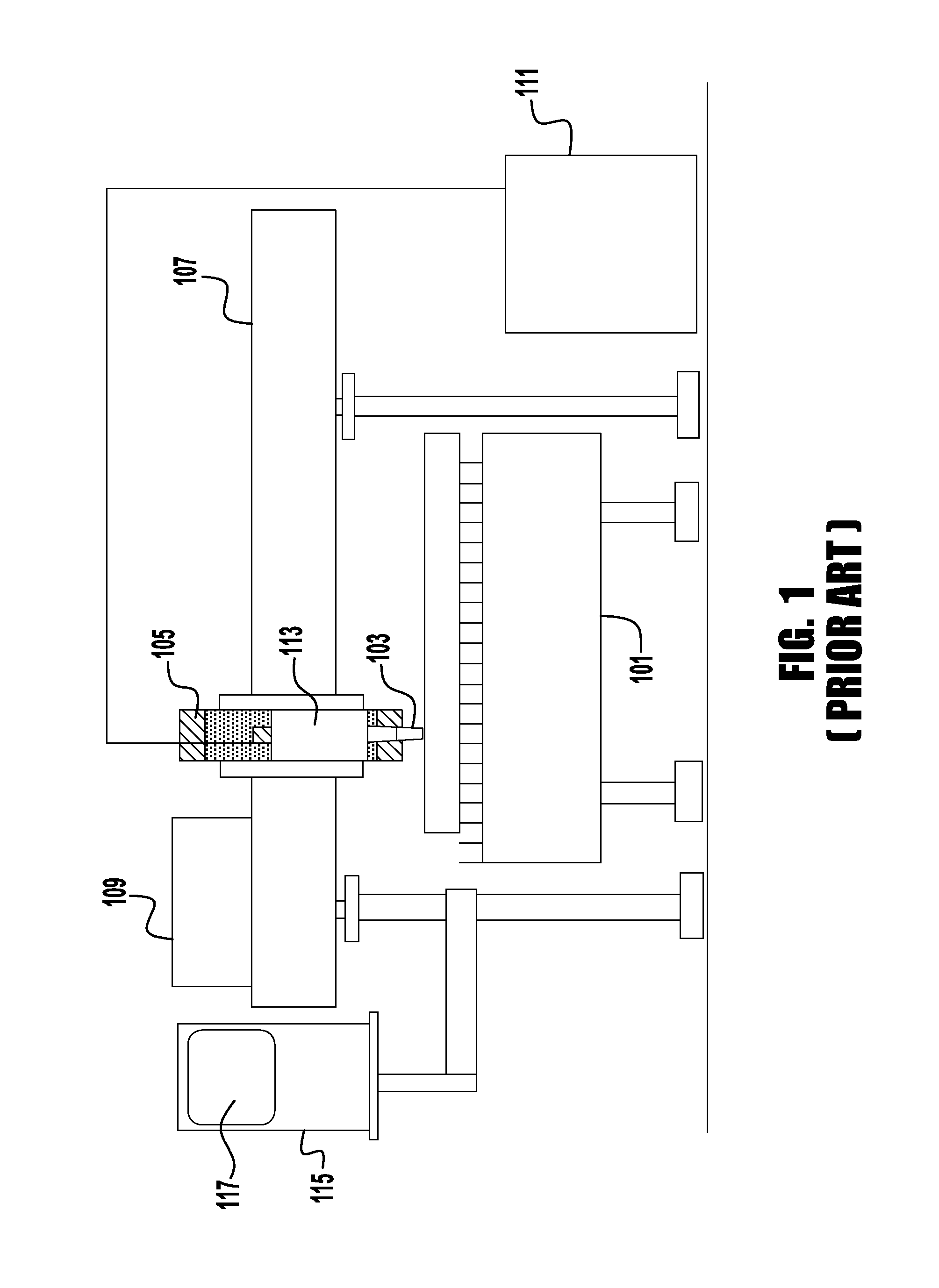
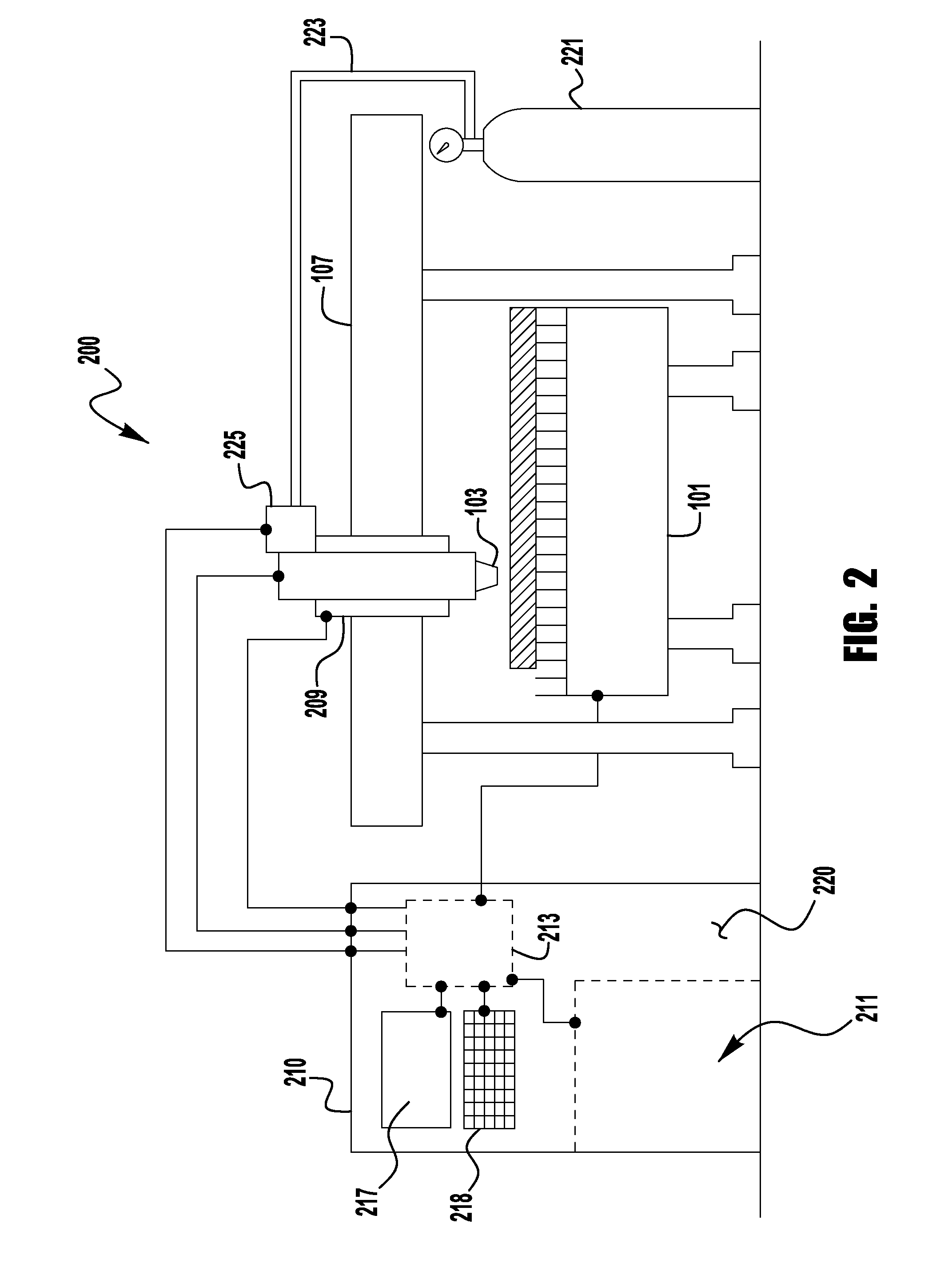
[0012]Turning now to FIG. 1, an known plasma cutting system 100 is depicted. The plasma torch system 100 includes a cutting table 101 and plasma torch 103. The construction and operation of cutting tables and plasma torches are well known by those of skill in the art and will not be discussed in detail herein. The system 100 can also use a torch height controller 105 which can be mounted to a gantry system 107. The system 100 can also include a drive system 109 which is used to pro...


PUM

PropertyMeasurementUnit
currentaaaaaaaaaa
pressureaaaaaaaaaa
thicknessaaaaaaaaaa

Abstract

An integrated plasma cutting system includes a plasma cutting power supply and a motion control device to move a torch along a desired cut path relative to a workpiece. The system also includes a torch height control device to adjust a gap between a tip of the torch and the workpiece and a gas control device to regulate a gas used in the integrated plasma cutting system. The system further includes a centralized controller that includes an integrated microprocessor architecture that controls a sequence of the plasma arc, controls the regulation of the gas used in the integrated plasma cutting system gases, and controls coordination of the movement of the torch along the cut path with adjusting the gap without aid of an intervening microprocessor architecture in any one of the plasma cutting power supply, the motion control device, the torch height control device and the gas control device.

Description

INCORPORATION BY REFERENCE[0001]The present application claims priority to Provisional Application 61 / 971,762, filed Mar. 28, 2014, which is incorporated herein by reference in its entirety.TECHNICAL FIELD[0002]Devices, systems, and methods consistent with the invention relate to cutting, and more specifically to devices, systems and methods for plasma cutting operations.BACKGROUND[0003]Currently, in an automated plasma cutting application the plasma power supply, motion and process controller, torch height control and gas control are separate pieces of equipment that are interconnected using cables to create a system used for controlling the plasma cutting process. Each individual component of this system has its own electronics and software / firmware executed by a microprocessor. This decentralized approach increases the system cost and installation time and complexity. Additionally, the interconnects between the components of such a system can also lead to significant limitations ...

Claims


Application Information

Patent Timeline
Patent Type & Authority Applications(United States)
IPC IPC(8): B23K10/00
CPCB23K10/006B23K10/00B23K37/0235B23K37/0461
Inventor HARKARE, SRIRAMWILLIAMS, CHRISTOPHER
Owner LINCOLN GLOBAL INC
Why Eureka
Try Eureka