Elastic membrane, substrate holding apparatus, and polishing apparatus

Active Publication Date: 2015-10-01
EBARA CORP
View PDF6 Cites 20 Cited by
  • Summary
  • Abstract
  • Description
  • Claims
  • Application Information

AI Technical Summary

Benefits of technology

[0019]Use of the above-described elastic membrane in the substrate holding apparatus of the polishing apparatus makes it possible to precisely control a polishing rate in a narrow area of a perip

Problems solved by technology

During polishing of the wafer, if a relative pressing force applied between the wafer and the polishing surface of the polishing pad is not uniform over the entire surface of the wafer, insufficient polishing or excessive polishing would occur depending on a force applied to each portion of the wafer.
However, since the above-described polishing pad has elasticity, the pressing force becomes non-uniform in a

Method used


Image

  • Elastic membrane, substrate holding apparatus, and polishing apparatus
  • Elastic membrane, substrate holding apparatus, and polishing apparatus
  • Elastic membrane, substrate holding apparatus, and polishing apparatus

Examples


Embodiment Construction

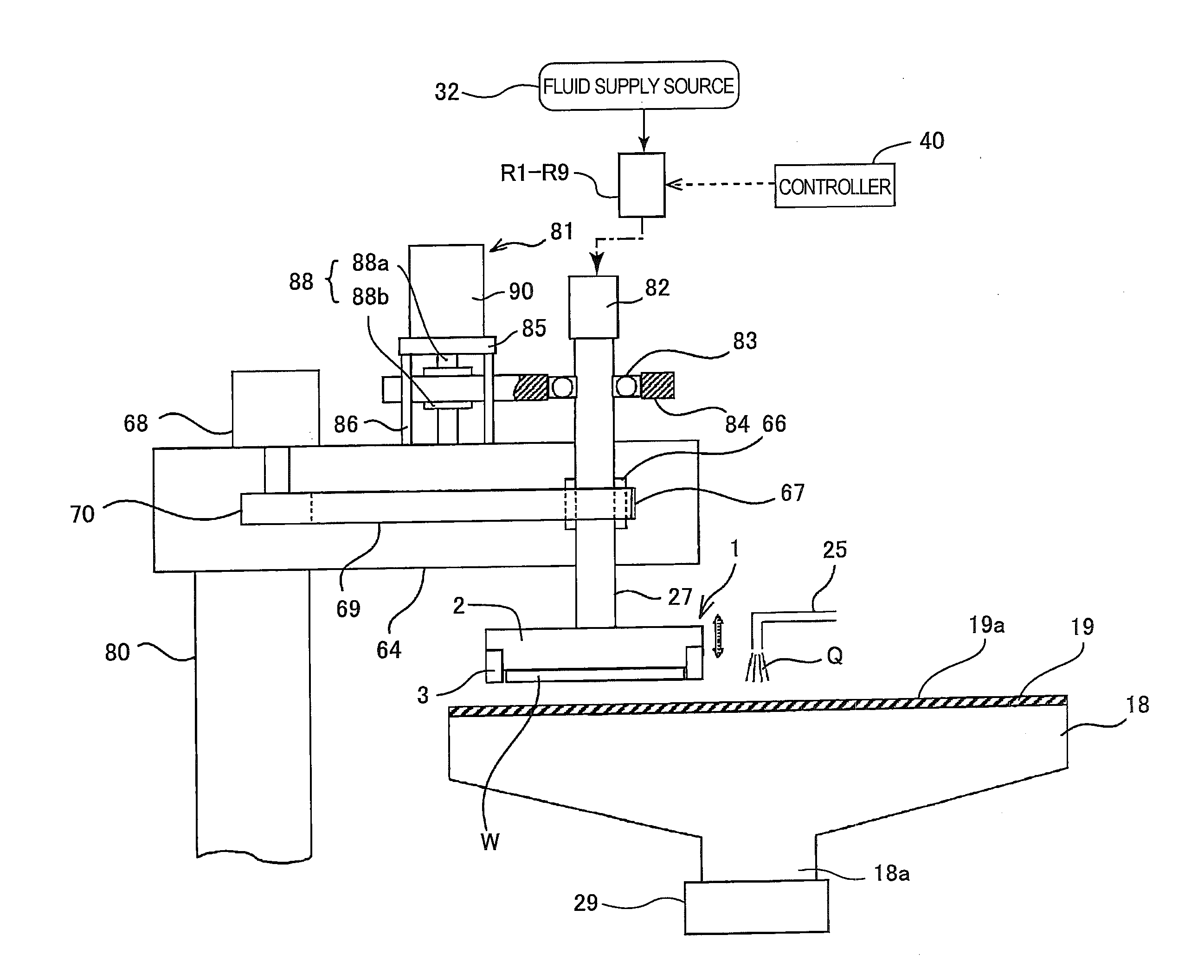
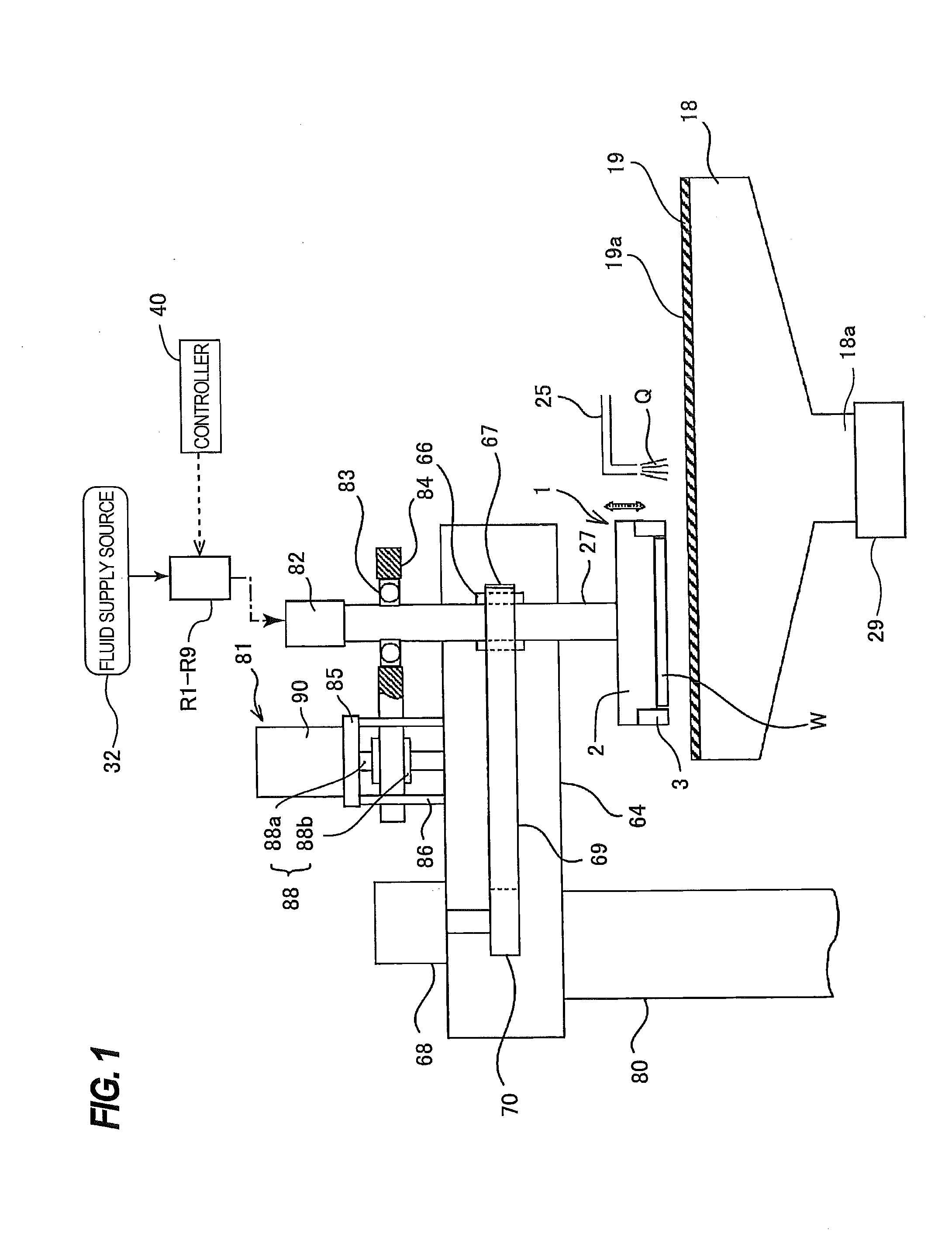
[0031]Embodiments will be described below with reference to the drawings. FIG. 1 is a view showing a polishing apparatus according to an embodiment. As shown in FIG. 1, the polishing apparatus includes a polishing table 18 for supporting a polishing pad 19, and a polishing head (or a substrate holding apparatus) 1 for holding a wafer W as an example of a substrate, which is an object to be polished, and pressing the wafer W against the polishing pad 19 on the polishing table 18.

[0032]The polishing table 18 is coupled via a table shaft 18a to a table motor 29 disposed below the polishing table 18, so that the polishing table 18 is rotatable about the table shaft 18a. The polishing pad 19 is attached to an upper surface of the polishing table 18. A surface 19a of the polishing pad 19 serves as a polishing surface for polishing the wafer W. A polishing liquid supply nozzle 25 is provided above the polishing table 18 so that the polishing liquid supply nozzle 25 supplies a polishing liq...


PUM


Abstract

An elastic membrane capable of precisely controlling a polishing profile in a narrow area of a wafer edge portion is disclosed. The elastic membrane includes a contact portion to be brought into contact with a substrate; a first edge circumferential wall extending upwardly from a peripheral edge of the contact portion; and a second edge circumferential wall having a horizontal portion connected to an inner circumferential surface of the first edge circumferential wall. The inner circumferential surface of the first edge circumferential wall includes an upper inner circumferential surface and a lower inner circumferential surface, both of which are perpendicular to the contact portion. The upper inner circumferential surface extends upwardly from the horizontal portion of the second edge circumferential wall, and the lower inner circumferential surface extends downwardly from the horizontal portion.

Description

CROSS REFERENCE TO RELATED APPLICATION[0001]This document claims priority to Japanese Patent Application Number 2014-066999 filed Mar. 27, 2014, the entire contents of which are hereby incorporated by reference.BACKGROUND[0002]With a recent trend toward higher integration and higher density in semiconductor devices, circuit interconnects become finer and finer and the number of levels in multilayer interconnect is increasing. In the fabrication process of the multilayer interconnects with finer circuit, as the number of interconnect levels increases, film coverage (or step coverage) of step geometry is lowered in thin film formation because surface steps grow while following surface irregularities on a lower layer. Therefore, in order to fabricate the multilayer interconnects, it is necessary to improve the step coverage and planarize the surface. It is also necessary to planarize semiconductor device surfaces so that irregularity steps formed thereon fall within a depth of focus in...

Claims


Application Information

Patent Timeline
IPC IPC(8): B24B37/30
CPCB24B37/30B24B7/228B24B37/10H01L21/68714H01L21/68721H01L21/304H01L21/461H01L21/683
Inventor FUKUSHIMA, MAKOTOYASUDA, HOZUMINAMIKI, KEISUKENABEYA, OSAMUTOGASHI, SHINGOYAMAKI, SATORUISONO, SHINTARO
Owner EBARA CORP
Why Eureka
Try Eureka