Heat pump system for vehicles

a heat pump and vehicle technology, applied in the field of vehicle heat pump system, can solve the problems of deteriorating heat exchange efficiency, affecting the heating performance and efficiency of the heat pump system, and the inability to dehumidify the interior of the vehicle, so as to minimize the pressure loss and flow noise of the refrigerant, and ensure the heating performance. the effect of smooth flow

Active Publication Date: 2015-10-01
HANON SYST
View PDF3 Cites 13 Cited by
  • Summary
  • Abstract
  • Description
  • Claims
  • Application Information

AI Technical Summary

Benefits of technology

[0019]Accordingly; the present invention has been made to solve the above-mentioned problems occurring in the prior arts, and it is an object of the present invention to provide a heat pump system for a vehicle, which includes a dehumidification line for supplying some of refrigerant circulating a refrigerant circulation line to an evaporator before the refrigerant is introduced into an exterior heat exchanger after passing a first expansion means so as to dehumidify the interior of the vehicle in a heat pump mode, thereby allowing the refrigerant to smoothly flow to the evaporator of a low pressure through the dehumidification line before the refrigerant is introduced into the exterior heat exchanger which has a higher pressure than the evaporator when the interior of the vehicle is dehumidified, and smoothly dehumidifying the inside of the vehicle.
[0021]According to the preferred embodiment of the present invention, the heat pump system for the vehicle includes the dehumidification line for supplying some of refrigerant circulating the refrigerant circulation line to the evaporator before the refrigerant is introduced into the exterior heat exchanger after passing the first expansion means so as to dehumidify the interior of the vehicle in the heat pump mode, thereby allowing the refrigerant to smoothly flow to the evaporator of a low pressure through the dehumidification line before the refrigerant is introduced into the exterior heat exchanger which has a higher pressure than the evaporator when the interior of the vehicle is dehumidified, and smoothly dehumidifying the inside of the vehicle.
[0022]Moreover, a bypass flow channel of the expansion valve to which the dehumidification line is connected is formed collinearly with an outlet of a first flow channel so as to minimize a pressure loss and a flow noise of the refrigerant.
[0023]Furthermore, a controller for controlling the on-off valve of the dehumidification line is mounted in order to judge frosting of the evaporator in the dehumidification mode or turn off the on-off valve when frosting is sensed, such that the heat pump system can prevent frosting of the evaporator.
[0024]Additionally, a pipe diameter of the dehumidification line is smaller than a pipe diameter of the refrigerant circulation line of the outlet side of the first expansion means or a pipe of the dehumidification line is connected in such a way as to be branched above a pipe of the refrigerant circulation line, such that a flow amount of the refrigerant branched from the refrigerant circulation line to the dehumidification line is relatively small so as to secure heating performance.

Problems solved by technology

In this instance, if temperature of the refrigerant introduced into the exterior heat exchanger 48 is higher than temperature of the outdoor air, in other words, if temperature of the refrigerant is low, the exterior heat exchanger 48 cannot absorb heat from the outdoor air and is deteriorated in heat-exchange efficiency due to frosting on the exterior heat exchanger 48, and hence, the heat pump system is deteriorated in heating performance and efficiency.
Therefore, it is impossible to dehumidify the interior of the vehicle.

Method used


Image

  • Heat pump system for vehicles
  • Heat pump system for vehicles
  • Heat pump system for vehicles

Examples


Embodiment Construction

[0035]Reference will be now made in detail to the preferred embodiment of the present invention with reference to the attached drawings.

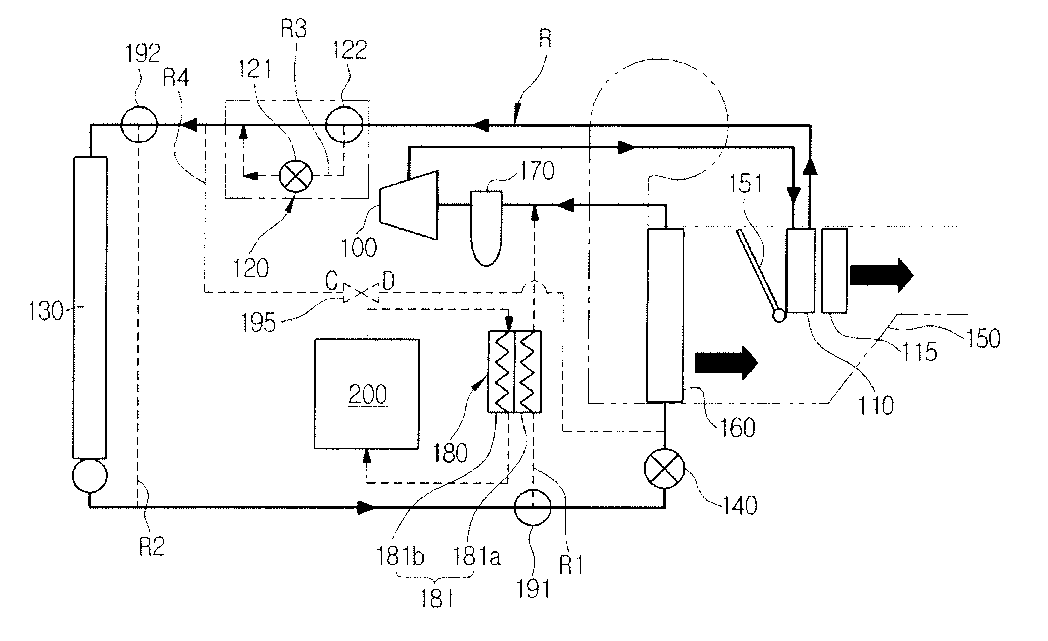
[0036]First, a heat pump system for a vehicle according to the present invention includes a compressor 100, an interior heat exchanger 110, first expansion means 120, an exterior heat exchanger 130, second expansion means 140, and an evaporator 160 which are connected on a refrigerant circulation line (R) in order, and is preferably applied to electric vehicles or hybrid vehicles.

[0037]Moreover, on the refrigerant circulation line (R), a bypass line (R1) bypassing the second expansion means 140 and the evaporator 160, an auxiliary bypass line (R2) bypassing the exterior heat exchanger 130, and an expansion line (R3) on which the first expansion means 120 is mounted are respectively connected in parallel.

[0038]Furthermore, a first direction changing valve 191 is mounted at a branching point of the bypass line (R1), a second direction changing valve 1...


PUM


Abstract

A heat pump system for a vehicle includes a dehumidification line for supplying some refrigerant circulating in a refrigerant circulation line to an evaporator before the refrigerant is introduced into an exterior heat exchanger after passing a first expansion means so as to dehumidify the interior of the vehicle in a heat pump mode, thereby allowing the refrigerant to smoothly flow to the evaporator at a low pressure through the dehumidification line before the refrigerant is introduced into the exterior heat exchanger which has a higher pressure than the evaporator when the interior of the vehicle is dehumidified, and smoothly dehumidifying the inside of the vehicle.

Description

BACKGROUND OF THE INVENTION[0001]1. Field of the Invention[0002]The present invention relates to a heat pump system for a vehicle, and more particularly, to a heat pump system for a vehicle, which includes a dehumidification line for supplying some of refrigerant circulating a refrigerant circulation line to an evaporator before the refrigerant is introduced into an exterior heat exchanger after passing a first expansion means so as to dehumidify the interior of the vehicle in a heat pump mode, thereby allowing the refrigerant to smoothly flow to the evaporator of a low pressure through the dehumidification line before the refrigerant is introduced into the exterior heat exchanger which has a higher pressure than the evaporator when the interior of the vehicle is dehumidified, and smoothly dehumidifying the inside of the vehicle.[0003]2. Background Art[0004]In general, an air conditioner for a vehicle includes a cooling system for cooling the interior of the vehicle and a heating sy...

Claims


Application Information

Patent Timeline
Patent Type & Authority Applications(United States)
IPC IPC(8): B60H1/32B60H3/02
CPCB60H3/024B60H1/3207B60H1/00921F25B5/02F25B5/04F25B6/04F25B2400/0403F25B2400/0409F25B2400/0411B60H1/3228
Inventor KANG, SUNG HOKIM, HAK KYUCHOI, YOUNG HOLEE, JUNG JAELEE, SANG KILIM, YOUN WOO
Owner HANON SYST
Why Eureka
Try Eureka