
Liquid dispenser

a dispenser and liquid technology, applied in the direction of liquid/fluent solid measurement, flexible cover, containers, etc., can solve the problems of bringing about contamination, contaminating liquid, and unacceptable contamination in the pressure chamber region, so as to reduce the risk of contamination, reduce the volume, and tighten the molar mass distribution

Active Publication Date: 2015-10-01
APTAR RADOLFZELL
View PDF5 Cites 4 Cited by
  • Summary
  • Abstract
  • Description
  • Claims
  • Application Information

AI Technical Summary

Benefits of technology

The invention provides a liquid dispenser that reduces contamination in the pressure chamber.

Problems solved by technology

The comparatively large surface area of the valve body which faces toward the valve chamber in the region of the valve plate leads to a problem, however.
It has thus been established that the conventional selection of material for the valve plate, specifically the use of thermoplastic elastomers (TPE), can lead to contamination of the liquid.
These additives tend to escape in small quantities from their carrier material over time and thereby bring about said contamination.
Since long periods of time can occasionally pass between discharging processes of a liquid dispenser of the generic type, an unacceptable degree of contamination can arise in the region of the pressure chamber and therefore in the part of the liquid waiting to be discharged.

Method used


Image

  • Liquid dispenser
  • Liquid dispenser
  • Liquid dispenser

Examples


Embodiment Construction

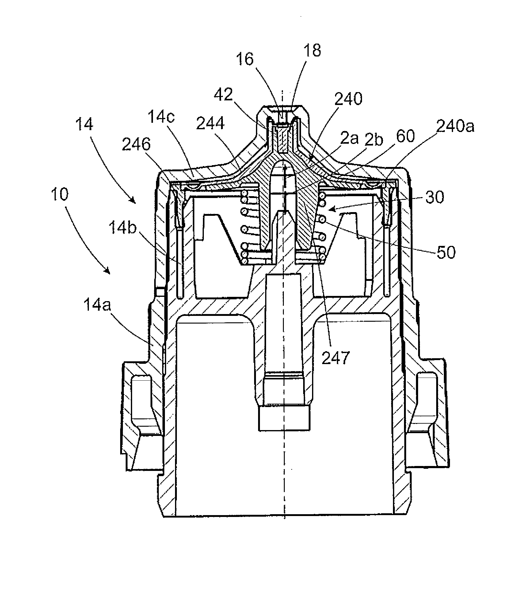
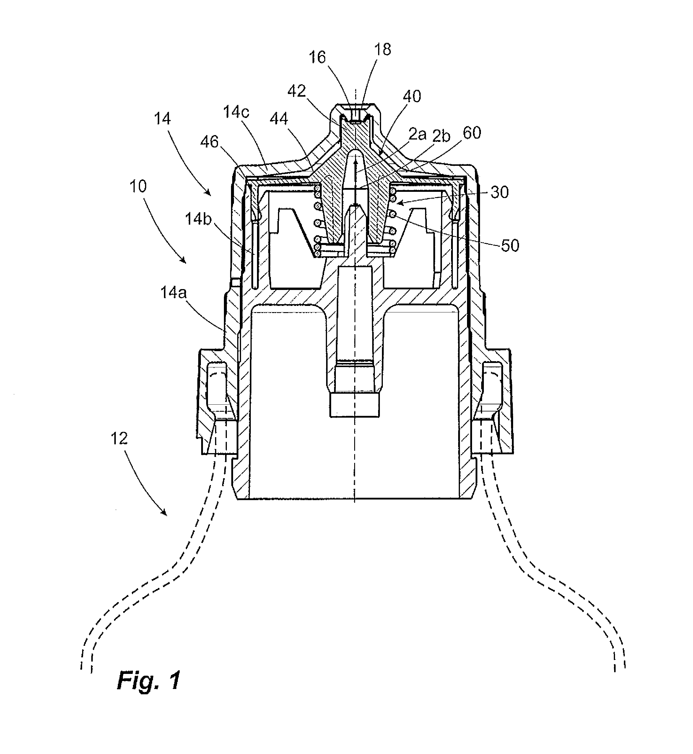
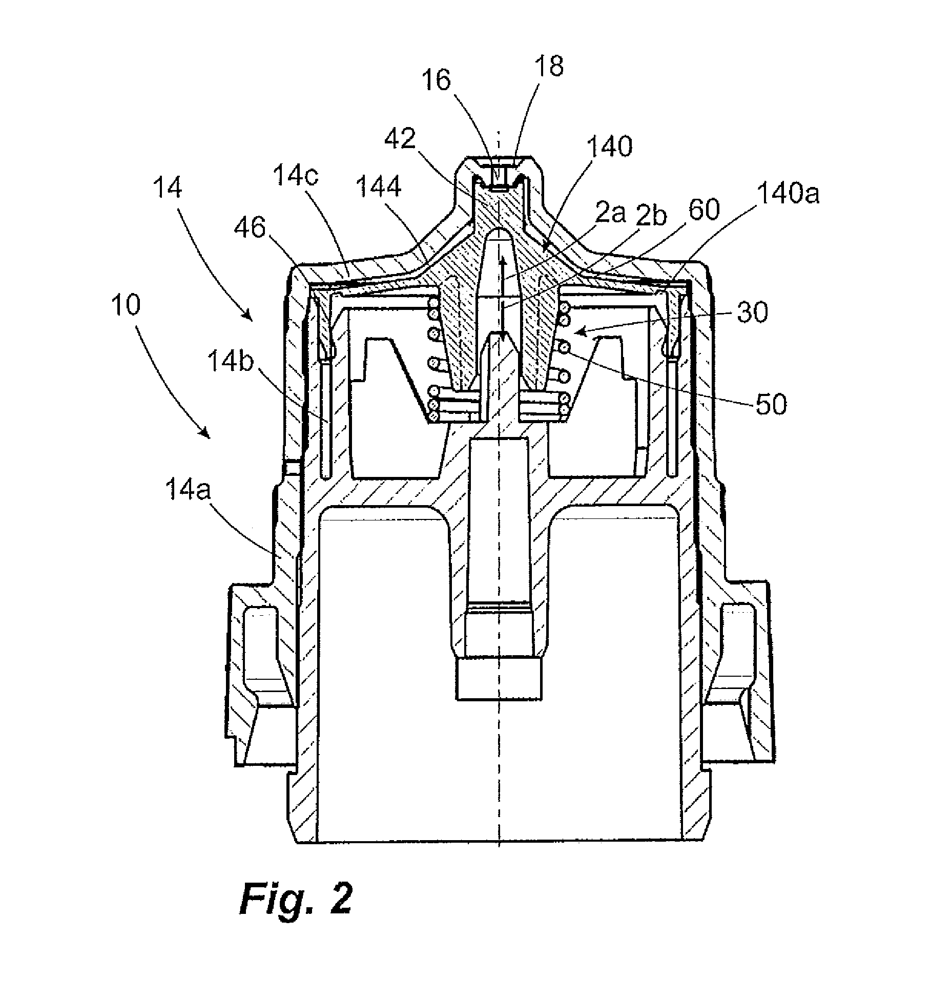
[0044]FIG. 1 shows a first liquid dispenser 10 according to the invention intended for discharging a pharmaceutical liquid in droplet form. This may be a pharmaceutical liquid for treating eyes of a patient, for example.

[0045]The liquid dispenser 10 comprises a bottle vessel 12, which serves as a liquid reservoir, and a discharge head 14. The discharge head 14 is provided with a discharge opening 16, which at the same time represents a valve opening 16 of an outlet valve 30 and which pierces through an outer housing 14a of the discharge head 14. The outlet valve 30 is configured as an outlet valve 30 which opens in a pressure-dependent manner.

[0046]For this purpose, a valve body 40 is arranged below the valve opening 16, with respect to the illustration of FIG. 1, said valve body having a valve pin 42 which is movable with respect to the outer housing 14a and which is arranged on the valve body 40 in such a manner that it can close the valve opening 16 in a closed position of the ou...


PUM


Abstract

Liquid dispenser for discharging pharmaceutical liquids, having a housing, an outlet opening and an outlet valve assigned to the outlet opening. The outlet valve includes a pressure chamber arranged upstream of a valve opening and delimited to one side by a valve plate of a valve body. By increasing the pressure in the pressure chamber, the valve can be opened. The pressure chamber has a flat form and has a large surface area in contact with liquid in relation to the volume.At least one portion of the valve plate which is in contact with liquid in the pressure chamber is of a valve plate material produced using metallocenes as catalysts.

Description

FIELD OF APPLICATION AND PRIOR ART[0001]The invention relates to a liquid dispenser for discharging pharmaceutical liquids, having a housing, an outlet opening and an outlet valve assigned to the outlet opening. In this case, the outlet valve of such a liquid dispenser of the generic type comprises, as main components, a valve opening which is connected upstream of the outlet opening or is identical to the outlet opening and a valve pin, the valve pin closing the valve opening in a closed position of the outlet valve and releasing the valve opening in an open position of the outlet valve. Furthermore, the outlet valve comprises a valve body, which has either the valve pin or the valve opening and which is displaceable at least partially with respect to the housing of the liquid dispenser in order to thereby make it possible to transfer the outlet valve between said closed position and said open position. A pressure chamber which is arranged upstream of the valve opening and is delim...

Claims


Application Information

Patent Timeline
Patent Type & Authority Applications(United States)
IPC IPC(8): B65D47/28B05B11/00
CPCB05B11/0072B65D47/283A61F9/0008B05B11/0067B05B11/047B65D47/18B65D47/2068B65D47/2081B65D65/38
Inventor RITSCHE, STEFAN
Owner APTAR RADOLFZELL
Learn More