Hydraulic hammer device for excavators

a hydraulic hammer and excavating technology, applied in mechanical machines/dredgers, portable drilling machines, manufacturing tools, etc., can solve the problems of significant yield loss with the conventional solution, low yield improvement in practice, and blowing to the ground rod and the ground, so as to improve the overall yield of the machine, the effect of improving the overall yield and reducing the pressure fluctuation

Inactive Publication Date: 2015-10-01
PARAMOUNT INT SERVICES
View PDF25 Cites 3 Cited by
  • Summary
  • Abstract
  • Description
  • Claims
  • Application Information

AI Technical Summary

Benefits of technology

[0013]The absence of floating parts must first be pointed out. In fact, the elements responsible for delivering blows (the cylinders) are integrally connected to the ripper and housed therein, so the impact is internal, i.e., on the same element which attacks the ground, the ripper itself. Use of moving parts, such as the ground rods of conventional hammers are thereby avoided, preventing problems due to tilted clearances and blows.
[0014]Another advantage to be pointed out is the use of energy and increase in yield compared to hammers described in the state of the art. In fact, when the first cylinder moves down, the second cylinder moves up and vice versa. Nevertheless, it must be taken into account that the cylinder that moves down always moves down faster than the cylinder that moves up. During normal operation, oil from the machine moves a first cylinder up, whereas the second cylinder moves down due to nitrogen pressure. The first cylinder sends a signal at the end of the upward movement so that the second cylinder also starts to move up, causing the first cylinder to fall. Given that the downward movement is faster than the upward movement, the cylinder that moves down makes an impact and waits to receive signal from the other cylinder. Therefore, the actual hammer-blow frequency is about twice that in a conventional hammer, and oil is always used by one of the two cylinders without needing return or oil accumulation chambers, improving the overall yield of the machine.
[0015]Typically, a piston does not have the same thrust at the start of the stroke as at the end. The energy chambers of both cylinders are communicated to prevent this. Hence, if the cylinders were linear cylinders, the pressure in both chambers would be about the same, therefore, the pressure would be kept constant in the stroke of both cylinders. Nevertheless, in practice the pressure in both chambers will not be 100% constant since, as mentioned, the cylinder that moves down does so faster than the cylinder that moves up. Nevertheless, the fluctuation of pressures is minimal, which significantly improves yield compared to conventional hammers, without changing the pressure from the machine and without sending the oil to the return tank.
[0016]Blow to the body of the ripper generates an upward reaction force. This force accumulates in the energy accumulator, preferably a pneumatic element, although other elements having similar characteristics are not ruled out. During use, reaction to the blow compresses the accumulator, i.e., loading it, whereas the accumulator is unloaded when blow is delivered, i.e., it decompresses, adding the accumulated force to that of the blow itself due to the cylinders, since the accumulator is aligned with the attacking shaft, as indicated. Furthermore, the accumulator advantageously dampens the transmission of vibrations to the rest of the machine.
[0017]Therefore, the device object of the invention improves the yield of known hydraulic or pneumatic hammers working on particularly hard grounds, furthermore improving their service life.
[0018]Furthermore, another advantage is that the combination of a ripper and a hammer allows both breaking up the ground (by means of the cylinder) and digging up the ground (by means of the ripper) something which is impossible up until now.

Problems solved by technology

In addition, when the piston moves up, the piston returns the oil to the excavator and loads a nitrogen chamber, such that nitrogen pressure strongly pushes against the piston, delivering blows to the ground rod and the ground accordingly.
Nevertheless, there is a significant yield loss with the conventional solution: it only uses between 50%-60% of the energy supplied by the excavator (i.e., the supplied oil).
Nevertheless, the actual yield is hardly improved in practice, since an improvement of said yield in the order of 5%-10% is virtually unnoticeable in use.
Another important technical problem of conventional hammers derives from the fact that the ground rod is a floating element independent of the piston, since it must logically be made of a much stronger structure.
If the piston was delivering blows directly, it would have to be made of special steel, and furthermore, in the event that it wore out, the entire assembly would have to be replaced, which would increase the cost of the system disproportionally.
Given the floating structure supported on special bushings, the ground rod generates side clearances during use which in a long run results in the ground rod tilting and blows being delivered to the piston in a non-planar manner, so if there is no constant maintenance, the ground rod deforms, causing the piston and therefore the hammer to break in many cases.
Nevertheless, its structure is not compact, rather they are elements exchangeable through force transmission means which, in practice, means that the implements for attacking the ground are floating implements and therefore would also tend to break along their connection and rotating shaft.
Another patent document combining both devices is U.S. Pat. No. 4,666,213, but as in the preceding case they are non-integrated superimposed devices that suffer from the same problems as conventional hammers.

Method used


Image

  • Hydraulic hammer device for excavators
  • Hydraulic hammer device for excavators
  • Hydraulic hammer device for excavators

Examples


Embodiment Construction

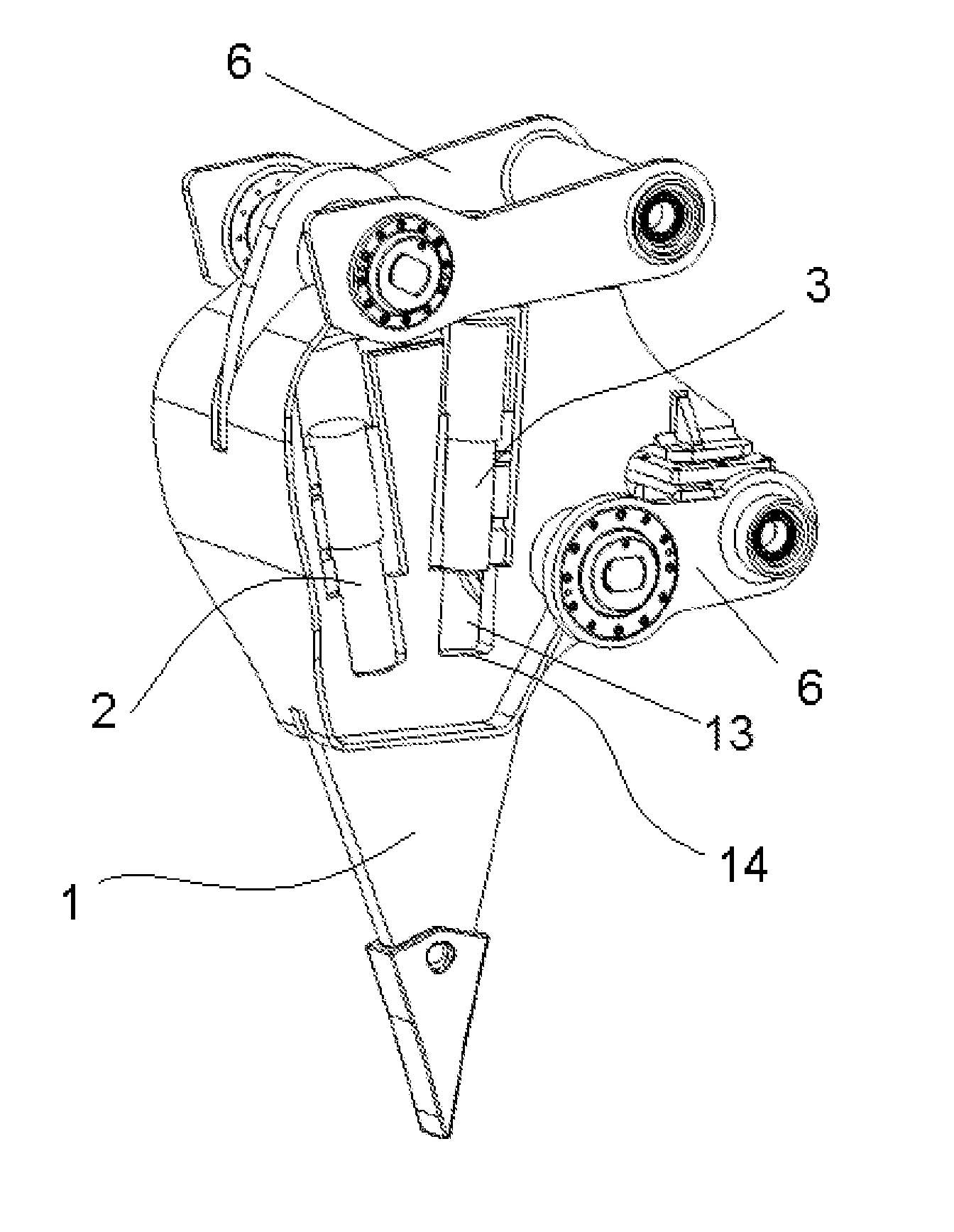
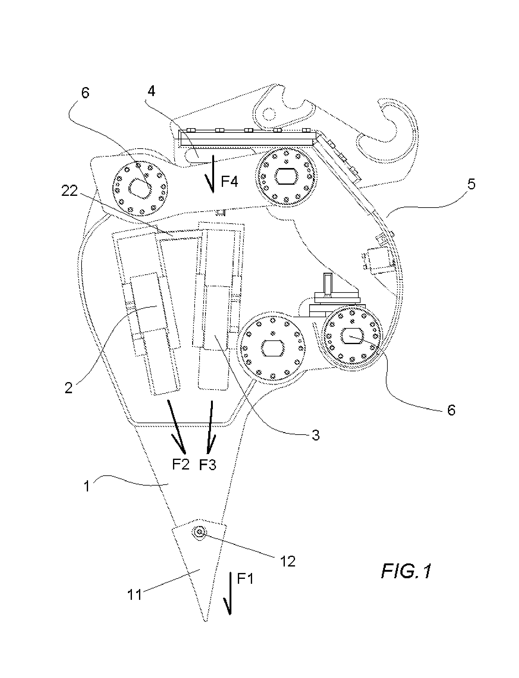
[0025]As can be seen in the attached drawings, the hydraulic hammer device for excavators object of the present invention is used for delivering blows to and digging up extremely hard grounds, such as rock (granite) and the like. The device essentially comprises a ripper (1) itself, at the lower end of which there is arranged a tooth (11) connected to the body of the ripper (1) by means of a bolt (12) or the like, such that said tooth (11) can be replaced if it wears out.

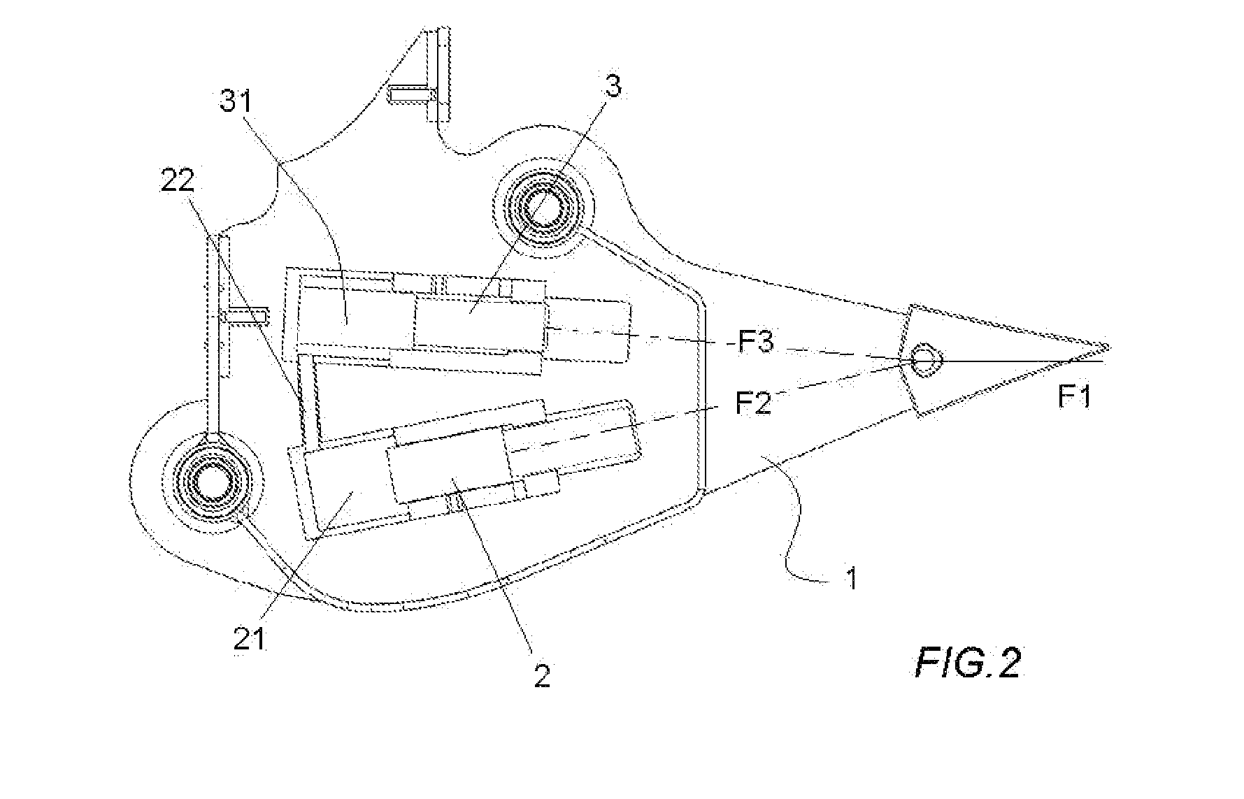
[0026]Inside the body of the ripper (1), in a space (13) provided for such purpose, there are housed two cylinders (2,3) integrally connected to the body of the ripper (1) and arranged with respect to one another such that the force vector (F2,F3) of both cylinders (2,3) is oriented towards one and the same point coinciding with the attack vector (F1) which attacks the bottom of the ripper and which in this embodiment coincides with the connection point (12) of the tooth (11) with the ripper (1).

[0027]In this practi...


PUM

PropertyMeasurementUnit
angleaaaaaaaaaa
angleaaaaaaaaaa
forceaaaaaaaaaa

Abstract

A hydraulic hammer device for excavators comprising at least one ripper (1) and an energy accumulator (4); where the energy accumulator (4) is located on the longitudinal shaft of the ripper (1) and integrally connected to said ripper (1); and where said shaft is on that which attacks the ground between the retracted and deployed positions of the ripper (1) and which is characterized in that it comprises a cylinder (2) or two cylinders (2,3) integrally connected to the ripper (1) inside same.

Description

[0001]The object of the present invention is a ripper-type hydraulic hammer device formed as an implement for an excavator which delivers blows to and digs up rock, concrete, asphalt, or any other type of ground and essentially consists of a hydraulic motor which receives oil flow and pressure from the excavator and is responsible for operating a series of elements hammering the ripper, giving it a movement which delivers blows to the ground.PRIOR ART[0002]Hydraulic hammers are extremely well-known in the field of public works as a basic implement for breaking hard grounds. These hammers are generally formed by an essentially cylindrical body internally housing a piston configured for delivering blows to a ground rod which, floating on at least one bushing, is responsible for attacking the ground.[0003]The ground rod has a vertical stroke. The operation of the hammer essentially starts from receiving oil from the excavator, putting pressure on the piston, such that it moves down ver...

Claims


Application Information

Patent Timeline
Patent Type & Authority Applications(United States)
IPC IPC(8): E02F5/32E02F3/96
CPCE02F3/966E02F5/323E02F9/2217
Inventor ARACAMA MARTINEZ DE LAHIDALGA, JAVIER
Owner PARAMOUNT INT SERVICES
Why Eureka
Try Eureka