Current sensor

a current sensor and sensor technology, applied in the field of current sensors, can solve the problems of reducing detection accuracy, increasing production man-hours, and difficulty in inserting the bus bar through the opening portion of the case, so as to prevent heat generation and maintain detection accuracy.

Inactive Publication Date: 2015-10-01
SUMITOMO WIRING SYST LTD
View PDF4 Cites 7 Cited by
  • Summary
  • Abstract
  • Description
  • Claims
  • Application Information

AI Technical Summary

Benefits of technology

[0016]In the exemplary embodiments, the opening portion is formed in at least one of the first case segment and the second case segment that constitute the case so as to have a cut-out shape that is open toward a direction orthogonal to a direction in which the detection target portion of the bus bar extends. It is possible to insert the detection target portion through the opening portion by inserting the detection target portion thereinto from a side of the opening of the cutout. Thereby, even if the bus bar is larger than the opening portion, it is possible to assemble the current sensor by inserting the detection target portion through the case and the magnetic core. As a result, it becomes unnecessary to connect the detection target portion to other bus bars, and thus it is possible to prevent the heat generation due to the contact resistance between the bus bars and to maintain the detection accuracy.

Problems solved by technology

However, it is often difficult to insert the bus bar through the opening portion of the case, as the bus bar has a complicated shape that sometimes has a width dimension that is larger than that of the opening portion or is sometimes provided with a large number of bent portions.
Then, there is a risk that the heat generation due to the contact resistance between the bus bars affects the magneto-electric conversion element, and thus the detection accuracy is lowered.
Moreover, the contact resistance depends on the tightening torque of a bolt for fixing the bus bars to each other, and therefore, there is a problem in that it is necessary to accurately control the tightening torque of the bolt and thus production man-hours increase.

Method used


Image

  • Current sensor
  • Current sensor
  • Current sensor

Examples


Embodiment Construction

[0027]Hereinafter, an exemplary embodiment will be described with reference to the drawings.

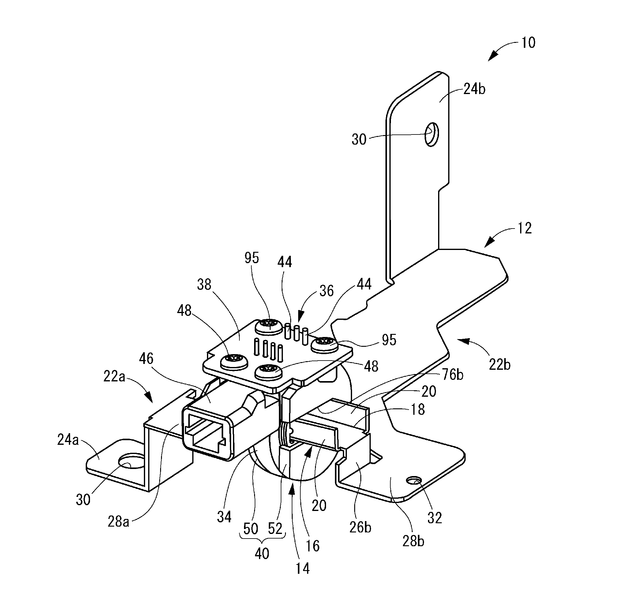
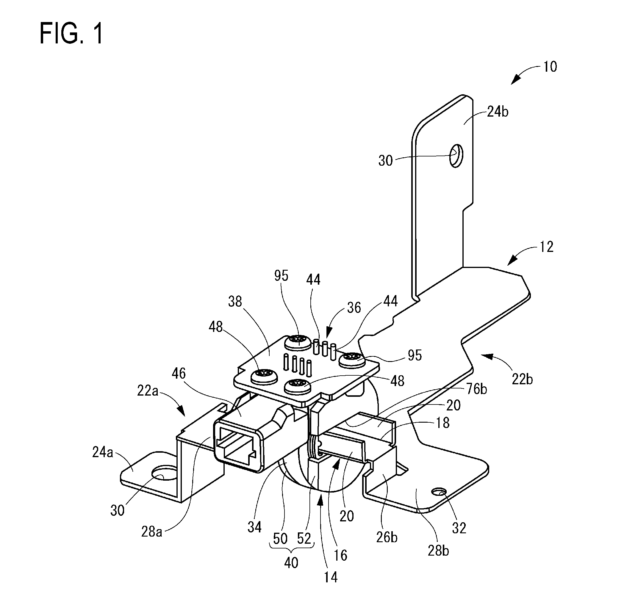
[0028]First, FIG. 1 and FIG. 2 show a current sensor 10 according to an exemplary embodiment. The current sensor 10 has a structure in which a sensor body 14 is assembled to a bus bar 12, and is configured to include the bus bar 12. For example, the bus bar 12 of the current sensor 10 is attached to a battery pack, a junction box, or the like.

[0029]FIG. 3 shows the bus bar 12. The bus bar 12 is an integrally shaped article formed by, for example, bending a punched metal plate. As a shape of the bus bar 12, any shape can be set depending on the required routing configuration of the electric circuit, or the like. The bus bar 12 of this embodiment is provided with a detection target portion 16 that extends with a certain width dimension (dimension in the vertical direction in FIG. 3). The detection target portion 16 is provided with a pair of raised portions 20 that is bent along bending lines 1...


PUM


Abstract

Provided is a current sensor capable of being assembled even if a bus bar inserted through a magnetic core has a complex shape that is difficult to insert through an opening portion of a case. A case includes a first case segment and a second case segment provided with opening portions having a cut-out shape that is open toward a direction orthogonal to a direction in which a detection target portion of a bus bar extends, and the case is assembled to the detection target portion by inserting the detection target portion into the opening portions from the direction orthogonal to the direction in which the detection target portion extends.

Description

TECHNICAL FIELD[0001]The exemplary embodiments relate to a current sensor for detecting a current flowing through a conductor, and a current sensor for detecting a current flowing through a bus bar serving as a conductor.BACKGROUND ART [0002]Conventionally, a current sensor has been used to detect a charging / discharging current of a battery of a car and to detect a current flowing between a battery and an inverter of a hybrid car or an electric car. As described in JP 2012-47563A, the current sensor has a structure in which a conductor such as a bus bar is inserted through an annular magnetic core and a magneto-electric conversion element such as a Hall element is disposed in a gap formed by cutting out a portion of the circumference of the magnetic core. The magneto-electric conversion element converts a magnetic flux generated by current flowing through the conductor into voltage signals, and thus the current flowing through the conductor is detected.[0003]Incidentally, in such a ...

Claims


Application Information

Patent Timeline
Patent Type & Authority Applications(United States)
IPC IPC(8): G01R15/14
CPCG01R15/148G01R15/202G01R15/207
Inventor NAKAJIMA, HIROKATSU
Owner SUMITOMO WIRING SYST LTD
Why Eureka
Try Eureka