Failure cause classification apparatus

a classification apparatus and failure cause technology, applied in the field of analyzing time series data obtained from sensors, can solve the problem of requiring a large amount of man-hours in order to achieve the effect of reducing the number of errors

Inactive Publication Date: 2015-10-01
HITACHI HIGH-TECH CORP
View PDF8 Cites 16 Cited by
  • Summary
  • Abstract
  • Description
  • Claims
  • Application Information

AI Technical Summary

Benefits of technology

[0006]Selecting deliberately the sensors for use in comparing the operation data at a time of mechanical failure against that in previous cases can raise the accuracy of failure identification.
[0011]According to the present invention, it is possible to select more simply than before the sensors considered effective for classifying failure causes. For example, the sensors deemed effective for classifying failure causes can be selected without mechanical knowledge.

Problems solved by technology

Furthermore, a huge amount of man-hours is required in order to select the sensors for each machine type and for each failure cause.

Method used


Image

  • Failure cause classification apparatus
  • Failure cause classification apparatus
  • Failure cause classification apparatus

Examples


first embodiment

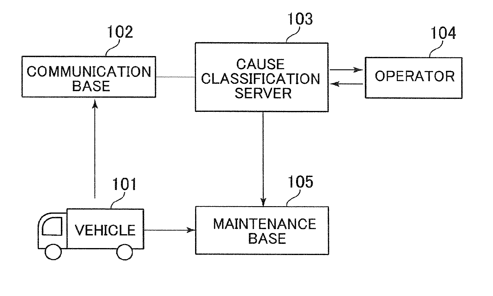
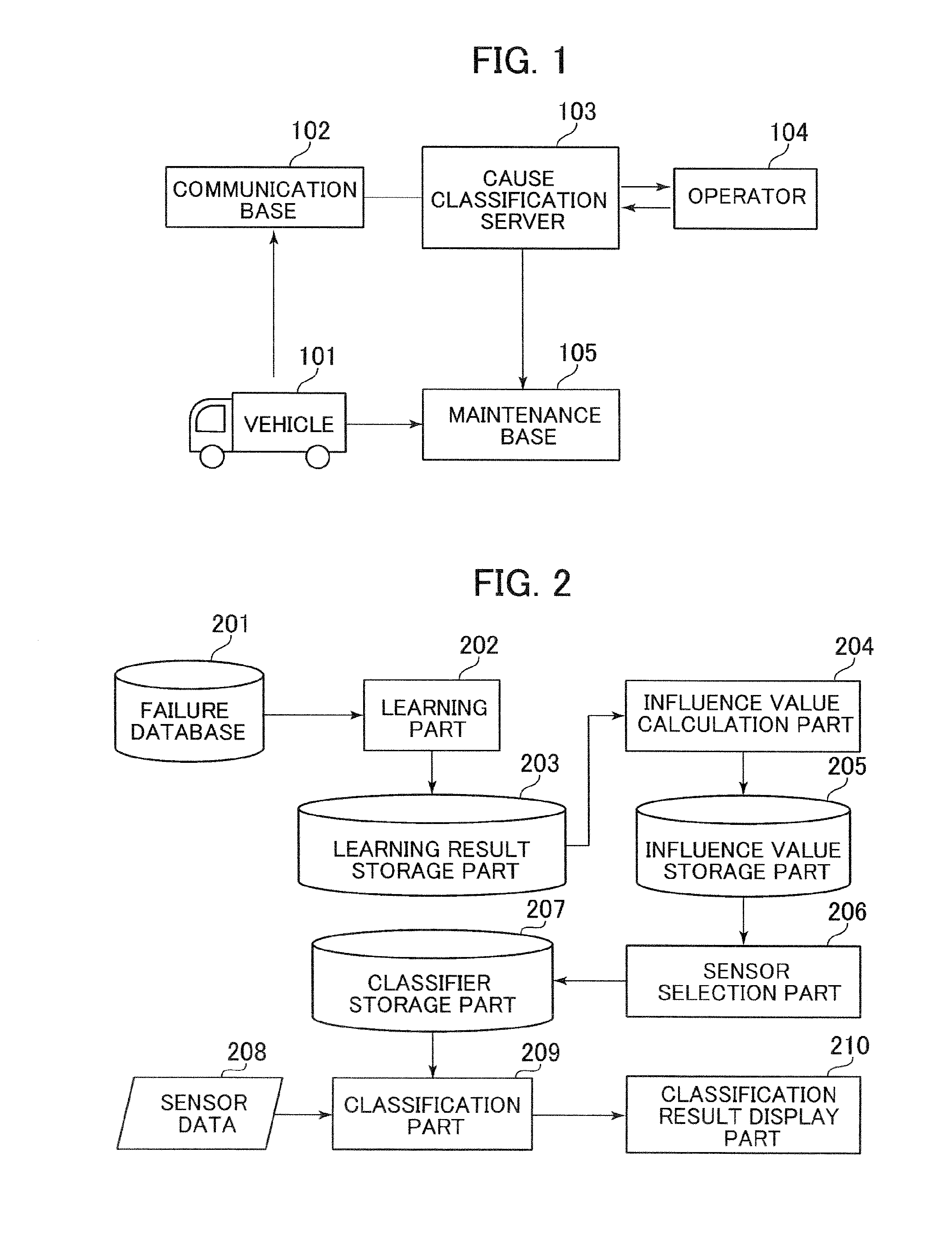
[0030]FIG. 1 is a diagram explaining a system of one embodiment of the present invention. The system of the present embodiment includes a vehicle 101, a communication base 102, a cause classification server 103, and a maintenance base 105. An operator 104 operates the cause classification server 103.

[0031]Numerous sensors are incorporated in the vehicle 101. At a time of failure the sensor data detected by the sensors are sent from the vehicle 101 via the communication base 102 and received by the cause classification server 103.

[0032]The cause classification server 103 classifies the received sensor data into possible failure causes and then transmits the result of the classification to the maintenance base 105. The settings for cause classification such as the selection of sensors have been made beforehand by the operator 104. The maintenance base 105 performs efficient maintenance work using the received information about the classified failure causes.

[0033]The vehicle 101, commu...


PUM


Abstract

Selection of sensors requires the knowledge of individual sensors mounted on a target machine and the knowledge of mechanical features of the machine. In the past, experts having mechanical knowledge selected the sensors. The present invention involves analyzing sensor data at e of machine failure, extracting features from the sensor data regarding each failure cause, and comparing the extracted features so as to clarify the difference between the sensor data about the failure causes and present an operator with the clarified difference thereby to support sensor selection. The invention makes it possible to select more simply than before the sensors considered effective for classifying failure causes. For example, the sensors deemed effective for classifying failure causes without mechanical knowledge can be selected.

Description

BACKGROUND OF THE INVENTION[0001]1. Field of the Invention[0002]The present invention relates to an apparatus and a method for analyzing time series data obtained from sensors.[0003]2. Description of the Related Art[0004]In business where commercial vehicles such as freight trucks are used, their utilization rate determines the profit and loss of the operation. This has given rise to a move to reduce downtime for maintenance by rapidly identifying the cause of a mechanical failure that has occurred.[0005]In the past, comparing the operation data when the machine failed against past failure data used to identify the causes of failure. In such cases the sensors for use upon the comparison are carefully selected so that possible failure causes can be classified with accuracy. JP-5363927-B, for example, states that the conditions required of the sensors to identify normal and failed states are obtained by combining multivariate analysis with mechanical knowledge.SUMMARY OF TEE INVENTION...

Claims


Application Information

Patent Timeline
Patent Type & Authority Applications(United States)
IPC IPC(8): G07C5/08B60K35/00G06Q10/00
CPCG07C5/0808B60K35/00G06Q10/20G05B23/0275G05B23/0281
Inventor ISHIKAWA, MASAYOSHISUZUKI, HIDEAKIHIRUTA, TOMOAKIMASUDA, TOSHIOKIKEGAWA, KEN
Owner HITACHI HIGH-TECH CORP
Why Eureka
Try Eureka