

Liquid crystal display device and method for driving same
- Summary
- Abstract
- Description
- Claims
- Application Information
AI Technical Summary
Benefits of technology
Problems solved by technology
Method used
Image

Examples
first embodiment
1. First Embodiment
[0119]
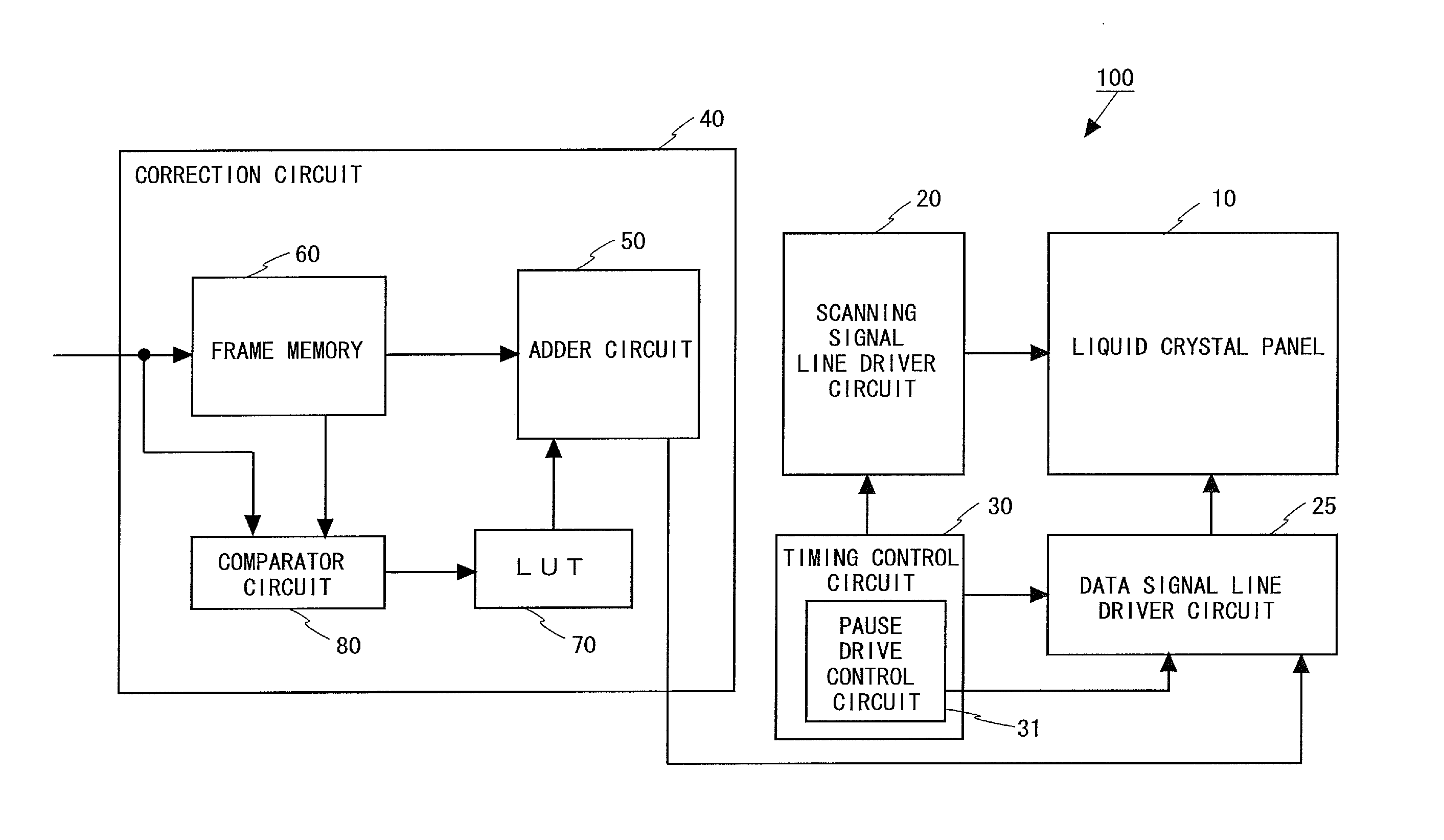
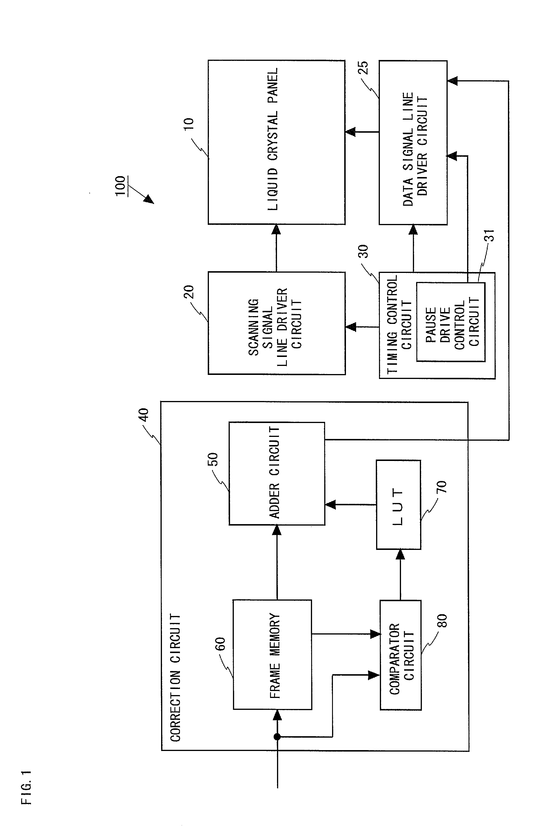
[0120]FIG. 1 is a block diagram illustrating the configuration of a liquid crystal display device 100 according to a first embodiment of the present invention. The liquid crystal display device 100 shown in FIG. 1 includes a liquid crystal panel 10, a scanning signal line driver circuit 20, a data signal line driver circuit 25, a timing control circuit 30, and a correction circuit 40.
[0121]The liquid crystal panel 10 has a plurality of pixel forming portions (not shown) arranged in a matrix of rows and columns. Moreover, the liquid crystal panel 10 has a plurality of scanning signal lines (not shown) and a plurality of data signal lines (not shown) formed crossing each other. Each scanning signal line is connected to pixel forming portions arranged in the same row, whereas each data signal line is connected to pixel forming portions arranged in the same column.
[0122]A horizontal synchronization signal and a vertical synchronization signal are inputted to the...
second embodiment
2. Second Embodiment
[0173]
[0174]FIG. 16 is a block diagram illustrating the configuration of a liquid crystal display device 200 according to a second embodiment of the present invention capable of pause drive. As with the liquid crystal display device 100 shown in FIG. 1, the liquid crystal display device 200 shown in FIG. 16 includes a liquid crystal panel 10, a scanning signal line driver circuit 20, a data signal line driver circuit 25, a timing control circuit 30, and a correction circuit 40. Among these components, the correction circuit 40 differs in configuration from that shown in FIG. 1. Accordingly, in FIG. 15, the same components as those shown in FIG. 1 are denoted by the same reference characters as those assigned to the components shown in FIG. 1, therefore, any descriptions thereof will be omitted, and different components will be described mainly. As shown in FIG. 16, the liquid crystal display device 200 uses an LUT 270 to be described later, in place of the LUT 70...
third embodiment
3. Third Embodiment
[0215]When the dielectric anisotropy of the liquid crystal changes because of a change in ambient temperature around the liquid crystal display device, the response speed of the liquid crystal display device changes conspicuously. Accordingly, if overshoot or undershoot drive is performed at low temperature using an LUT having stored correction values set at room temperature, the response speed of the liquid crystal is slower at low temperature, and therefore, cannot be increased sufficiently, so that display cannot be provided with desired grayscale values. On the other hand, if overshoot or undershoot drive is performed at high temperature, overly emphasized display is provided because the response speed of the liquid crystal is faster at high temperature. Therefore, liquid crystal display devices for use in a wide range of temperatures preferably have a plurality of different LUTs for their respective temperature ranges so that optimized overshoot drive can be ...
PUM
 Abstract
Description
Claims
Application Information