Handling system and method of operating a handling system

Active Publication Date: 2015-10-08
J SCHMALZ GMBH
View PDF5 Cites 3 Cited by
  • Summary
  • Abstract
  • Description
  • Claims
  • Application Information

AI Technical Summary

Benefits of technology

[0021]The system may utilize a central control unit (especially a memory programmable storage—MPS) to control the at least one vacuum generator. The vacuum generator receives process data from the central control device. However, the operating data is referenced by the vacuum generator directly from the recognition unit of the respective connected handling device, so as to effect proper control and vacuum supply. Onl

Problems solved by technology

This may require extensive programming steps or time-consuming process inputs.
In addition, when a new handling device is add

Method used


Image

  • Handling system and method of operating a handling system
  • Handling system and method of operating a handling system

Examples


Embodiment Construction

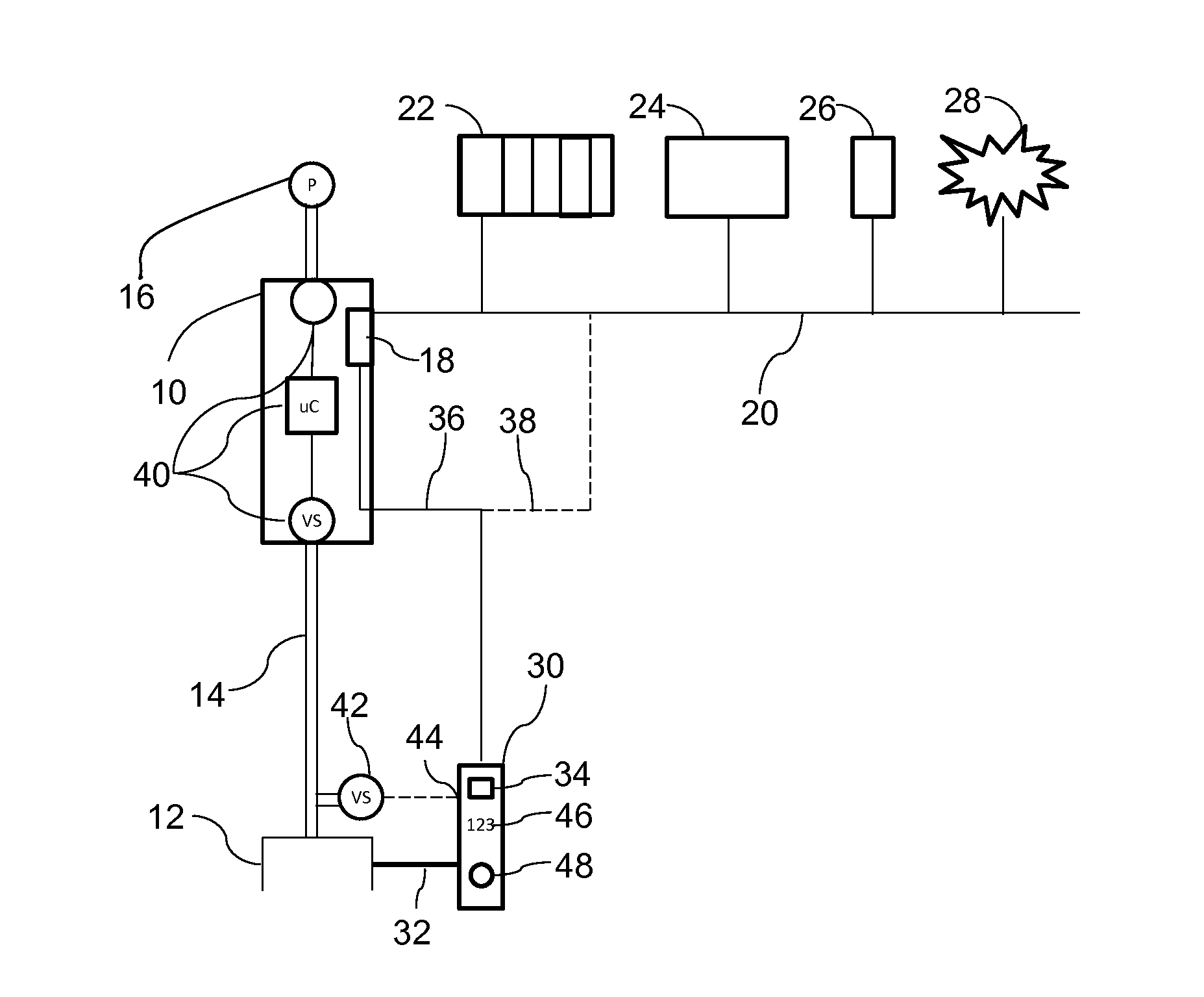
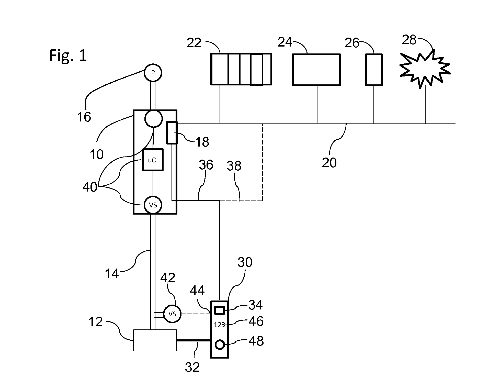
[0030]Further details of the invention will be described in greater detail below with reference to the accompanying figures. FIG. 1 shows a handling system with a vacuum generator 10 and an operating unit. In the example shown in FIG. 1, the operating unit is a vacuum gripper's formed vacuum handling device 12, which is pressure connected over a vacuum line 14 to a vacuum outlet of the vacuum generator 10. In one embodiment, the vacuum generator 10 may be formed as an ejector driven by compressed air supply 16. The system may advantageously include a plurality of vacuum generators connected to associated vacuum handling devices.

[0031]The vacuum generator 10 has a sub-control unit 18 which controls the operating state of the vacuum generator 10. The vacuum generator 10 or its sub-control unit 18 is connected to a field bus 20, to which other vacuum generators may also be connected. The field bus 20 is connected to a central control device 22 which can properly control the vacuum gene...


PUM


Abstract

A handling system having at least one vacuum generator and an associated vacuum handling device connected to and operable via the vacuum generator. The vacuum handling device is provided with an individually assigned recognition unit including a memory device in which operating data for the vacuum handling device is storable and can be read out. Each vacuum generator has a respective sub-control unit adapted to control the vacuum generator depending on data transmitted from the recognition unit. The memory device of the recognition unit can be read out directly from the sub-control unit.

Description

CROSS-REFERENCE TO RELATED APPLICATION[0001]This application is based upon and claims priority to German Patent Application No. DE 102014206308.6, filed on Apr. 2, 2014.BACKGROUND OF THE INVENTION[0002]1. Field of the Invention[0003]The present invention relates, generally, to handling systems used such as in production or processing lines and, more specifically, to a handling system for handling and / or for the further transport of workpieces.[0004]2. Description of the Related Art[0005]Handling systems known in the related art are typically built of several functional units, in particular one or more vacuum generators and operated vacuum handling devices. In operation, the individual functional units need to be coordinated with one another. Thus, operating parameters of the handling apparatus, for example, need to known in order to facilitate control in accordance with the vacuum generator. As is known in the related art, vacuum production needs to be connected to a bus system whic...

Claims


Application Information

Patent Timeline
IPC IPC(8): B25J15/06B25J19/02
CPCB25J19/02B25J15/0616B25J15/0483B25J15/0675
Inventor HOLECEK, THOMASDUNKMANN, WALTER
Owner J SCHMALZ GMBH
Why Eureka
Try Eureka