Method of manufacturing multi-layered propellant grains

a technology of propellant grains and propellant grains, which is applied in the direction of nitrocellulose explosive compositions, explosives, weapons, etc., can solve the problems of difficult to obtain satisfactory, large space and energy expenditure of equipment, and difficult operation, and achieve the effect of different burning rates and low viscosity

Active Publication Date: 2015-10-08
GENERAL DYNAMICS ORDNANCE & TACTICAL SYST CANADA VALLEYFIELD INC
View PDF14 Cites 11 Cited by
  • Summary
  • Abstract
  • Description
  • Claims
  • Application Information

AI Technical Summary

Benefits of technology

[0012]According to one aspect of the disclosure, there is provided a method of manufacturing a multi-layered propellant grain comprising the steps of providing a first propellant formulation; providing a die configured to provide a structure having an outer shell and a hollow interior when material is extruded therethrough; extruding the first propellant formulation through said die to produce a first propellant layer having an outer shell defining a hollow interior in the form of a passageway having open ends; providing a second propellant formulation, said second propellant formulation being of low viscosity; injecting said second propellant formulation into said passageway defined by said first propellant layer to form a second propellant layer disposed in said passageway; and hardening said second propellant layer, wherein the first and second propellant layers have different rates of burning.

Problems solved by technology

This equipment requires the use of a significant amount of space and energy.
As result, it is expensive to operate and often difficult to obtain satisfactory results.

Method used


Image

  • Method of manufacturing multi-layered propellant grains
  • Method of manufacturing multi-layered propellant grains
  • Method of manufacturing multi-layered propellant grains

Examples


Embodiment Construction

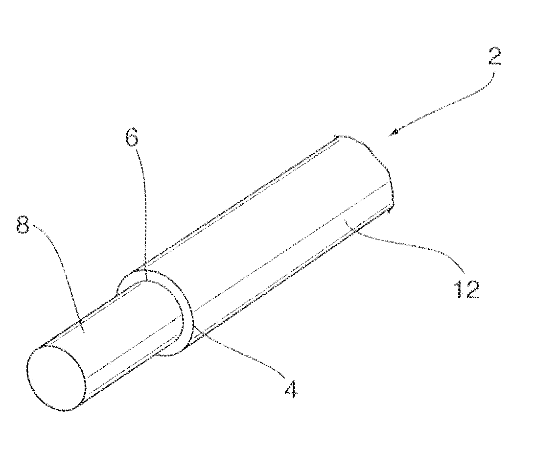
[0024]The present disclosure is directed to a method of producing multi-layered propellant grains. As a person skilled in the art will appreciate, an optimized performance is achieved for a multi-layered propellant where a maximum operational pressure is obtained upon combustion of a first layer followed by a second maximum operational pressure peak at the maximum operating pressure generated by the subsequent combustion of a second layer that has a faster burning rate than that of the first layer. A characteristic of the optimized performance can be better burning progressivity. The energy transferred in projectile motion is optimized by the maximum pressure maintained during a longer period of time in the barrel. The production of multi-layered propellant grains through co-extrusion techniques can lead to increased muzzle velocity and other outcomes such as flat temperature coefficient where the propellant will generate the same muzzle energy at cold and hot temperature; and insen...


PUM

PropertyMeasurementUnit
viscosityaaaaaaaaaa
diameteraaaaaaaaaa
diameteraaaaaaaaaa

Abstract

A method of manufacturing a multi-layered propellant grain is provided. The method of the present disclosure simplifies the setup necessary to produce multi-layered propellants by using industrial equipment that is more energy and space efficient than the machinery that is conventionally employed for such processes. The method comprises providing a first propellant formulation; providing a die configured to provide a structure having an outer shell and a hollow interior when material is extruded therethrough; extruding the first propellant formulation through said die, to produce a first propellant layer having an outer shell defining a hollow interior in the form channel having open ends; providing a second propellant formulation, said second propellant formulation being of low viscosity; injecting said second propellant formulation into said channel defined by said first propellant layer to form a second propellant layer disposed in said channel; and hardening said second propellant layer. The first and second propellant layers have different rates of burning.

Description

CROSS-REFERENCE TO RELATED APPLICATION[0001]The present application claims the benefit of priority to U.S. Provisional Application Ser. No. 61 / 866,748, filed on Aug. 16, 2013, the contents of which are herein incorporated by reference in their entirety.TECHNICAL FIELD[0002]The present disclosure generally relates to a method of manufacturing propellants used in propulsion systems for conventional ammunition.BACKGROUND[0003]Solid propellants produce hot gases when combusted. The production of hot gases creates pressure that drives propulsion systems for conventional ammunition of all calibers. The pressure generated in a gun tube accelerates projectiles. The objective for obtaining optimal performance is to maximize the projectile acceleration in the gun barrel for as long as possible without surpassing the mechanical failure stress level of the gun barrel. Attempts have been made to achieve a gas generation rate of the gun propellant charge inside the chamber of a gun system to prov...

Claims


Application Information

Patent Timeline
Patent Type & Authority Applications(United States)
IPC IPC(8): C06B21/00B29C48/40B29C48/475
CPCC06B21/0075F42B5/16F42B33/00C06B25/18C06B45/105C06B45/12B29C48/09B29C48/21B29C48/40B29C48/475B29C48/11
Inventor DURAND, SIMONPARADIS, PIERRE-YVESLEPAGE, DANIEL
Owner GENERAL DYNAMICS ORDNANCE & TACTICAL SYST CANADA VALLEYFIELD INC
Why Eureka
Try Eureka