
Flexible underfill compositions for enhanced reliability

a technology of underfill composition and reliability, applied in the direction of transportation and packaging, other chemical processes, semiconductor/solid-state device details, etc., can solve the problem of cte mismatch-induced stress generation

Active Publication Date: 2015-10-08
INTEL CORP
View PDF4 Cites 0 Cited by
  • Summary
  • Abstract
  • Description
  • Claims
  • Application Information

AI Technical Summary

Benefits of technology

The new underfill compositions significantly reduce electrical failures and outgassing, providing enhanced reliability and environmental safety by improving the matrix toughness and minimizing contamination.

Problems solved by technology

Such CTE mismatch-induced stresses may be generated during the repeated heat cycles during the various processing operations.

Method used


Image

  • Flexible underfill compositions for enhanced reliability
  • Flexible underfill compositions for enhanced reliability
  • Flexible underfill compositions for enhanced reliability

Examples


process example 1

Reaction Process Example 1

[0010]

Such a polymer intermediate may stain processing equipment and walls.

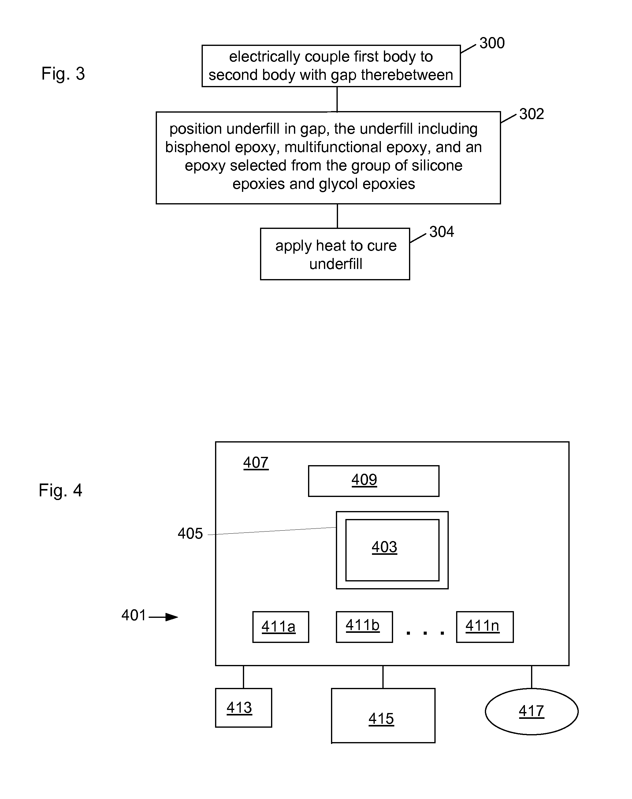
[0011]Certain embodiments relate to underfill compositions that are formulated to inhibit the formation of intermediates that contaminate the environment, as well as reduce the occurrence of electrical failures of large die BGA packages caused by underfill fillet cracking, and improve reliability.

[0012]In certain embodiments, a conventional aliphatic epoxy such as that set forth in the reaction process example 1 is replaced with an aliphatic epoxy component having a different chemical structure. Such a different aliphatic epoxy may, in certain embodiments, be selected from silicone epoxy and glycol epoxy structures.

[0013]An underfill composition in accordance with one such group of embodiments includes the use of a silicone epoxy together with other epoxies. Such other epoxies may include a variety of suitable bisphenol epoxies and multifunctional epoxies. Multifunctional epoxies inc...


PUM

PropertyMeasurementUnit
temperatureaaaaaaaaaa
weight percentaaaaaaaaaa

Abstract

Underfill materials for fabricating electronic devices are described. One embodiment includes an underfill composition including an epoxy mixture, an amine hardener component, and a filler. The epoxy mixture may include a first epoxy comprising a bisphenol epoxy, a second epoxy comprising a multifunctional epoxy, and a third epoxy comprising an aliphatic epoxy, the aliphatic epoxy comprising a silicone epoxy. The first, second, and third epoxies each have a different chemical structure. Other embodiments are described and claimed.

Description

RELATED ART[0001]In certain conventional electronic assembly manufacturing procedures, a die and a package substrate are brought into electrical contact with one another using solder bumps. A reflow operation is carried out by heating to a temperature greater than the melting point of the solder, and a solder connection is made between the pads on the die and pads on the substrate. A gap remains between the die and the substrate. A material such as a polymer is then typically placed into the gap between the chip and substrate, as an underfill encapsulant. One example of a package substrate is known as a ball grid array (BGA). BGA packages have a plurality of solder bumps located on an opposite surface that the die is attached to. Another reflow operation is carried out by heating to a temperature greater than the melting point of the solder bumps on the BGA package, and a solder connection is made between the package substrate and the board.[0002]FIG. 1 illustrates certain features ...

Claims


Application Information

Patent Timeline
Patent Type & Authority Applications(United States)
IPC IPC(8): C08G59/02C07F7/08
CPCY10T428/31515C07F7/0852C08G59/02H01L21/563H01L23/293H01L24/16H01L24/73H01L24/92H01L2224/16227H01L2224/73204H01L2224/92125H01L2924/15311H01L2924/3512C08G59/3254C08G59/38H01L2224/16225H01L2924/14H01L2224/05573H01L2224/05568H01L2924/00014C07F7/0838C08L23/0884H01L2924/00H01L2224/05599
Inventor XU, DINGYINGANANTHAKRISHNAN, NISHADONG, HONGMANEPALLI, RAHUL N.RARAVIKAR, NACHIKET R.CONSTABLE, GREGORY S.
Owner INTEL CORP
Learn More