Organic electroluminescent element and electronic device
a technology of electroluminescent elements and electronic devices, which is applied in the direction of solid-state devices, semiconductor devices, thermoelectric devices, etc., can solve the problems of deterioration rate of elements, difference in decomposition rate of organic materials generated simultaneously with light emission, etc., and achieve the effect of suppressing the lowering of display quality
- Summary
- Abstract
- Description
- Claims
- Application Information
AI Technical Summary
Benefits of technology
Problems solved by technology
Method used
Image
Examples
embodiment (first embodiment)
1. Embodiment (First Embodiment) of the Organic Electroluminescent Element
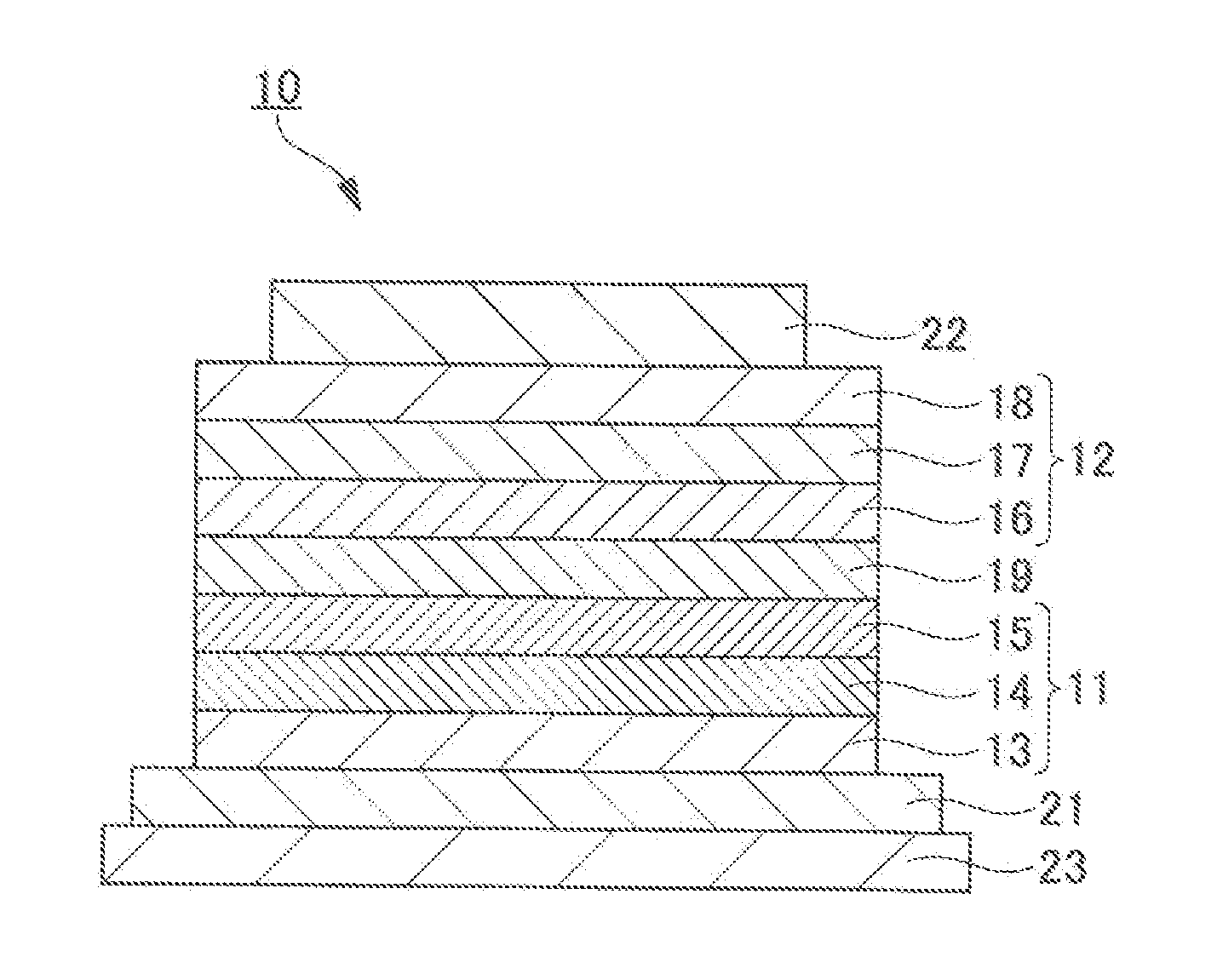
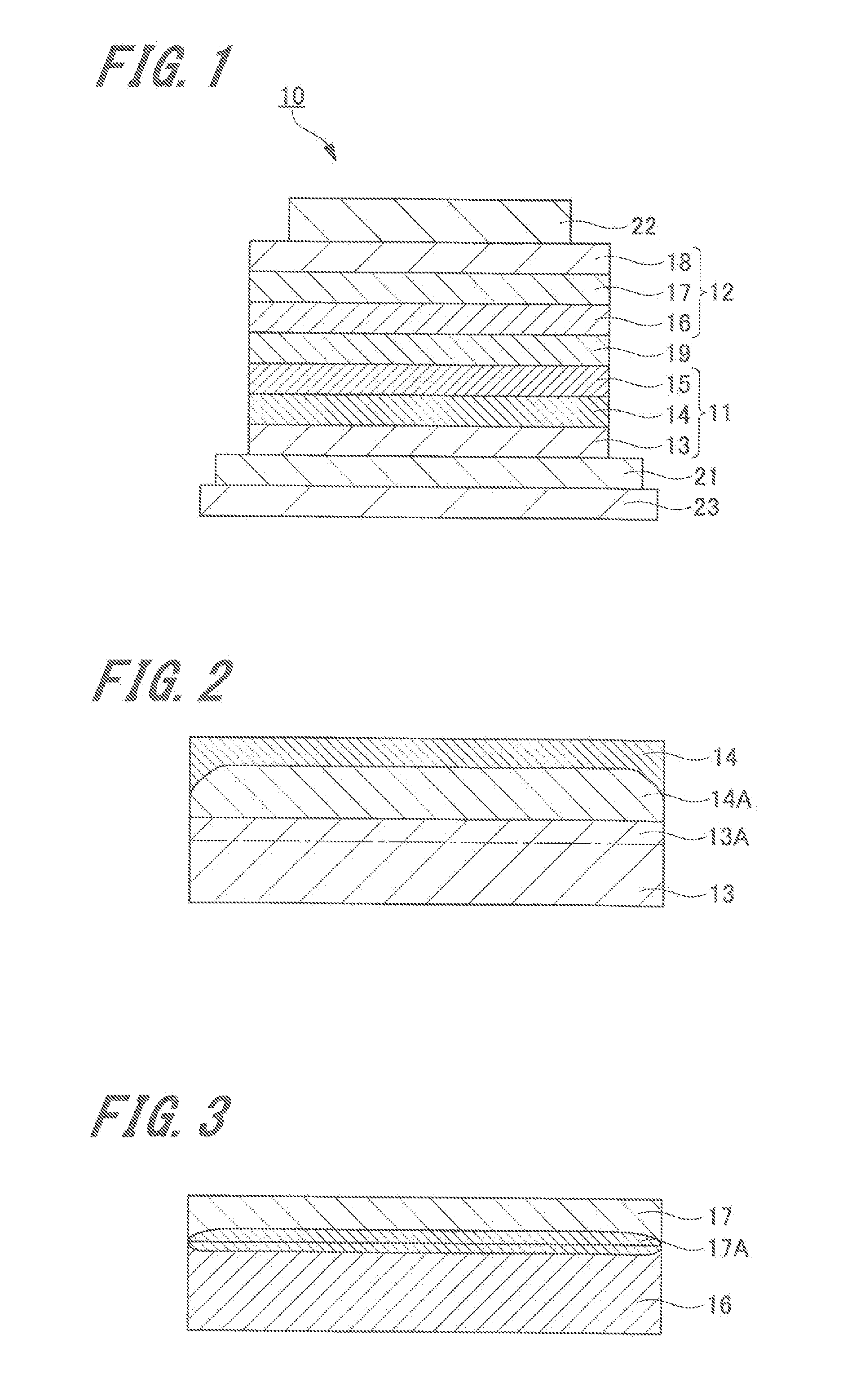
[0037]Hereinafter, the specific embodiment of the organic electroluminescent element (organic EL element) of the present invention will be explained. FIG. 1 shows the configuration of the organic EL element of the first embodiment.
[Configuration of Organic EL Element]
[0038]The organic EL element 10 shown in FIG. 1 has an anode 21, a first light-emitting unit 11, am intermediate connector layer 19, a second light-emitting unit 12, and a cathode 22. In addition, these layers are all provided on a substrate 23.
[0039]In the organic EL element 10, the anode 21 is formed on the substrate 23, and the first light-emitting unit 11 is formed on the anode 21. Furthermore, an intermediate connector layer 19 is formed on the first light-emitting unit 11, and a second light-emitting unit 12 is formed on the intermediate connector layer 19. Moreover, a cathode 22 is formed on the second light-emitting unit 12.
[0040]The above...
fifth embodiment
5. Embodiment of Electronic Device (Fifth Embodiment)
[Lighting Device-1]
[0315]Next, a lighting device will be explained as one embodiment of an electronic device where the organic EL element of the above first embodiment to the fourth embodiment is used.
[0316]The organic EL element used for a lighting device may be designed to impart a resonator structure to the organic EL element each having the configuration of the above first to fourth embodiments. The purpose of using of the organic EL element to be constituted as the resonator is a light source of an optical storage medium, a light source of an electrophotographic copying machine, a light source of an optical communication processor, a light source of a photosensor, and the like, and is not limited thereto. Furthermore, the element may be used for the above uses by laser oscillation.
[0317]Note that the materials used for the organic EL element can substantially be applied to the organic EL element which generates a white light ...
example
[0324]Hereinafter, the present invention will be specifically explained by referring examples, and the present invention is not limited thereto.
[0325]Each organic EL element of Samples 101 to 112 was manufactured so that an area of the light-emitting region was 5 cm×5 cm. Hereinafter, the configurations and manufacturing procedures of each light-emitting thin film laminated body of Samples 101 to 112 will be shown.
[0326]In addition, the configurations of the organic EL elements of Samples 101 to 105 are shown in Table 1. Furthermore, the configurations of the organic EL elements of Samples 106 to 112 are shown in Table 2.
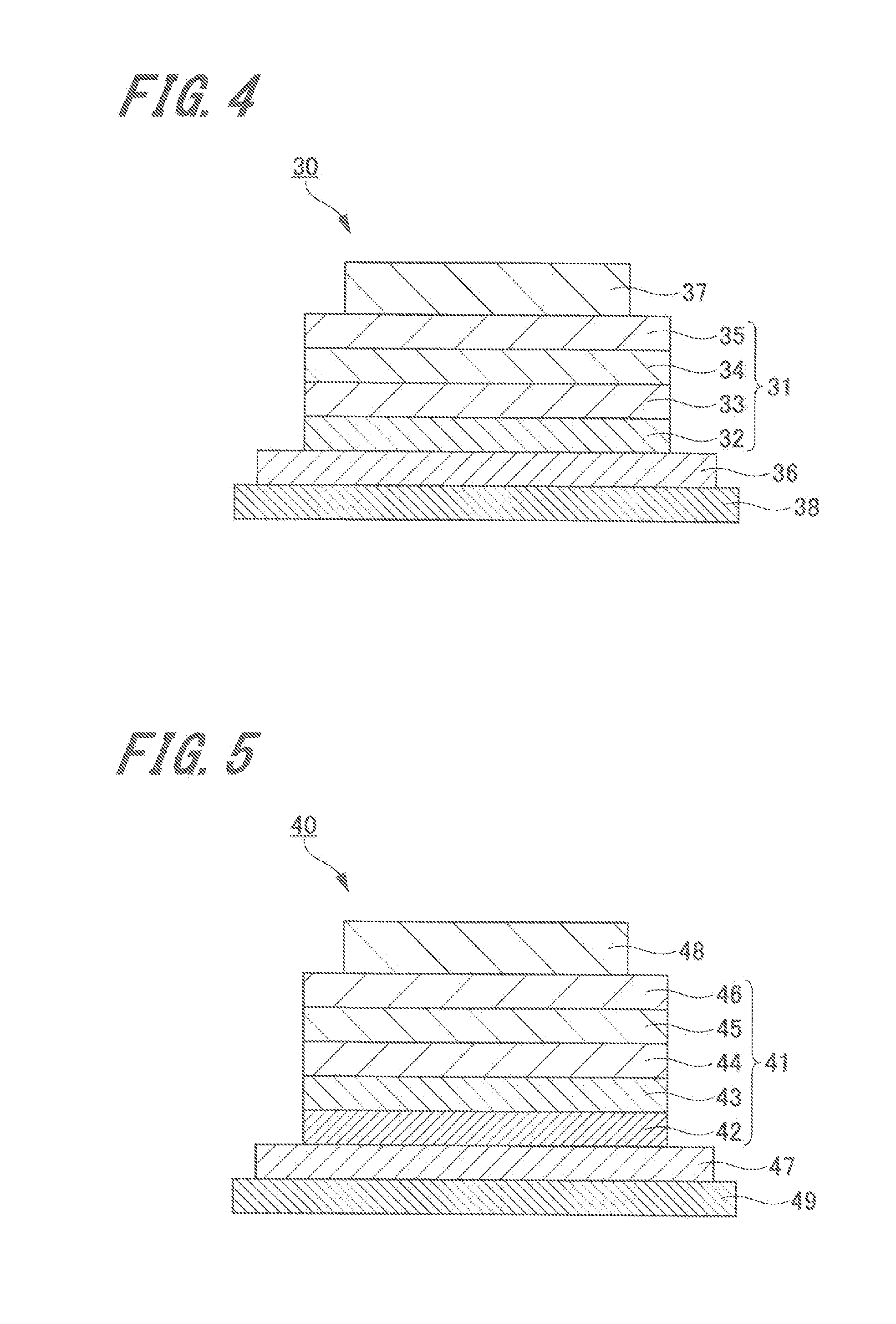
[0327]Samples 101 to 102, and 105 are the organic EL elements having the configuration shown in the above FIG. 1, Samples 103 to 104 are the organic EL elements having the configuration shown in the above FIG. 5, and Samples 106 to 112 are the organic EL elements having the configuration shown in the above FIG. 6.
[Producing the Organic EL Element of Sample 101]
(Anod...
PUM
 Abstract
Description
Claims
Application Information
 - R&D
- Intellectual Property
- Life Sciences
- Materials
- Tech Scout
- Unparalleled Data Quality
- Higher Quality Content
- 60% Fewer Hallucinations
Browse by: Latest US Patents, China's latest patents, Technical Efficacy Thesaurus, Application Domain, Technology Topic, Popular Technical Reports.
© 2025 PatSnap. All rights reserved.Legal|Privacy policy|Modern Slavery Act Transparency Statement|Sitemap|About US| Contact US: help@patsnap.com


