Supercharge Your Innovation With Domain-Expert AI Agents!

Harness assembly

a technology of harness assembly and assembly plate, which is applied in the direction of insulated conductors, cables, conductors, etc., to achieve the effect of improving soldering efficiency and quality

Inactive Publication Date: 2015-10-08
MOLEX INC
View PDF7 Cites 1 Cited by
  • Summary
  • Abstract
  • Description
  • Claims
  • Application Information

AI Technical Summary

Benefits of technology

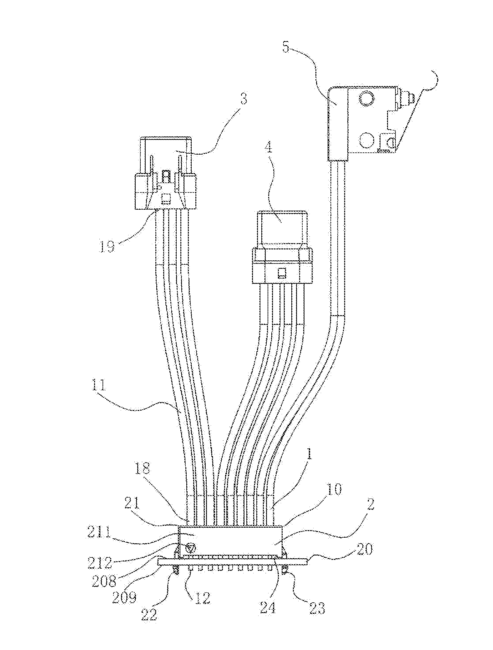
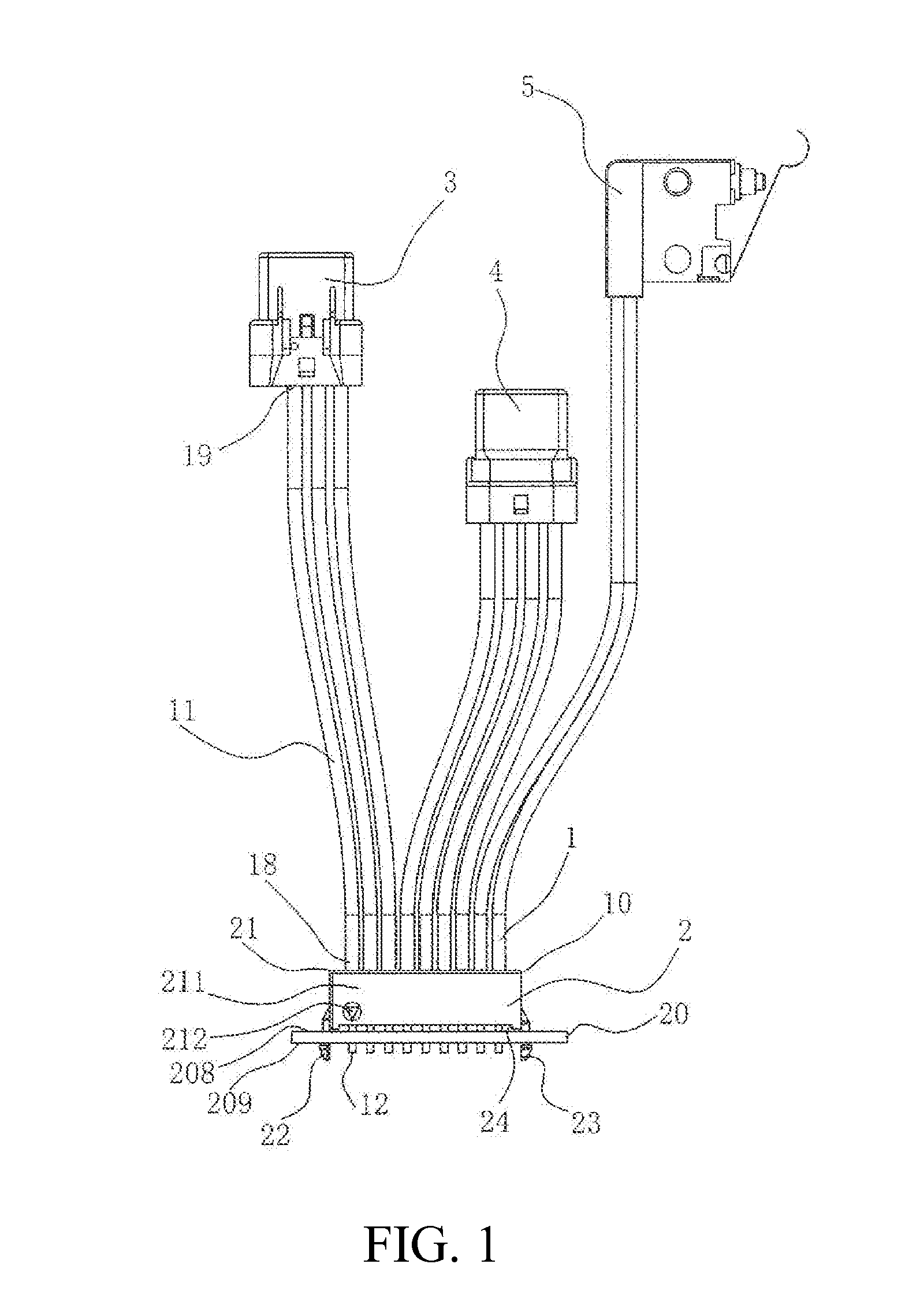
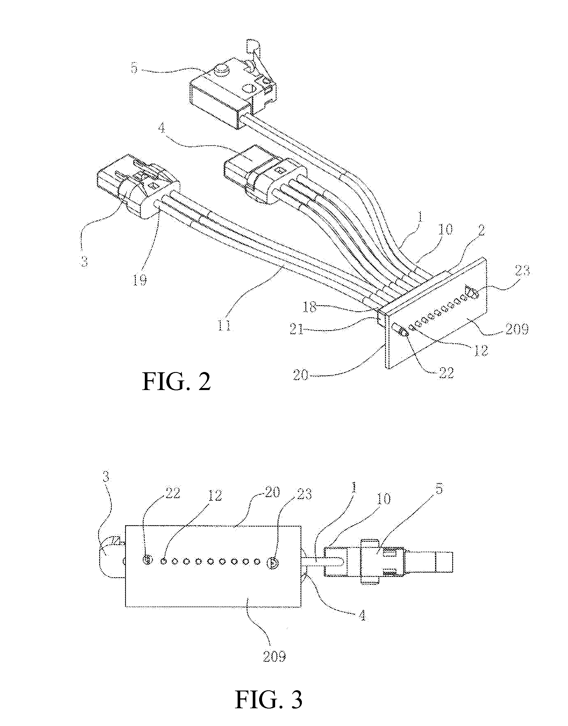
The technical effect of the harness assembly described in this patent text is that it ensures that wires are properly inserted into soldering positions on a circuit board at one time, improving both soldering efficiency and quality. Additionally, the positioning parts on the wires prevent damage to the soldered dots between the wires and the circuit board.

Problems solved by technology

The spacer in this existing design only has function that soldering ends of the wires are bundled and secured so as to facilitate soldering operation, but when the cable connector assembly is to perform alignment and soldering, if the spacer is accidentally rotated by 180°, it is easy to solder the wires in an upper row to soldering pads on a bottom surface of a circuit board and the wires in a lower row to soldering pads on a top surface of the circuit board, so the cable connector assembly does not have the function of preventing improper insertion.

Method used


Image

  • Harness assembly
  • Harness assembly
  • Harness assembly

Examples


Embodiment Construction

[0022]While the Present Disclosure may be susceptible to embodiment in different forms, there is shown in the Figures, and will be described herein in detail, specific embodiments, with the understanding that the Present Disclosure is to be considered an exemplification of the principles of the Present Disclosure, and is not intended to limit the Present Disclosure to that as illustrated.

[0023]As such, references to a feature or aspect are intended to describe a feature or aspect of an example of the Present Disclosure, not to imply that every embodiment thereof must have the described feature or aspect. Furthermore, it should be noted that the description illustrates a number of features. While certain features have been combined together to illustrate potential system designs, those features may also be used in other combinations not expressly disclosed. Thus, the depicted combinations are not intended to be limiting, unless otherwise noted.

[0024]In the embodiments illustrated in ...


PUM

PropertyMeasurementUnit
sizeaaaaaaaaaa
shapeaaaaaaaaaa
structureaaaaaaaaaa

Abstract

A harness assembly comprises a plurality of wires and a positioning part formed around the wires by means of molding. Each wire comprises an extension section and a naked section provided at a first end of the extension section. Each extension section comprises at least one core conductor and an insulative sheath covering an outer periphery of the at least one core conductor, the naked sections formed by baring and exposing the core conductors outside and are capable of being soldered to soldering pads of the circuit board. The positioning part comprises a main body portion formed around the wires by means of molding and two positioning legs provided on the main body portion in an asymmetry manner, the naked sections of the wires are arranged between the two positioning legs. The first positioning leg corresponds to the first positioning hole of the circuit board, and the second positioning leg corresponds to the second positioning hole of the circuit board.

Description

REFERENCE To RELATED APPLICATIONS[0001]The Present Disclosure claims priority to prior-filed Chinese Patent Application No. 201420165817.X, entitled “Cable Connector Assembly,” filed on 4 Apr. 2014 with the Chinese Patent Office. The content of the aforementioned Patent Application is incorporated in its entirety herein.BACKGROUND OF THE PRESENT DISCLOSURE[0002]The Present Disclosure relates, generally, to a harness assembly, and, more particularly, to a harness assembly which can prevent improper insertion.[0003]Chinese Patent Application No. 02295247.0, the content of which is hereby incorporated herein in its entirety, discloses a cable connector assembly which comprises a base, a cover body, and a cable connecting module. The cover body is assembled on the base. The cable connecting module is assembled between the base and the cover body, and comprises a cable, a plurality of terminals, a plurality of shielding plates and a spacer. The cable has a plurality of wires, the each wi...

Claims


Application Information

Patent Timeline
Patent Type & Authority Applications(United States)
IPC IPC(8): H01R4/02H01B7/00H01R12/53
CPCH01R4/027H01B7/0045H01R12/53H01R12/7052H01R13/64
Inventor LI, YUE-YOUCHEN, SHUI-NENG
Owner MOLEX INC
Features
  • R&D
  • Intellectual Property
  • Life Sciences
  • Materials
  • Tech Scout
  • Unparalleled Data Quality
  • Higher Quality Content
  • 60% Fewer Hallucinations
Learn More