Balancing pockets

a technology of balancing pockets and drum rotor wheels, which is applied in the direction of liquid fuel engines, marine propulsion, vessel construction, etc., can solve the problems of weakening the mechanical stability of the molded part, low efficiency of such drum rotor fans, and complex installation of balancing weights

Active Publication Date: 2015-10-15
EBM PAPST MULFINGEN GMBH & CO KG
View PDF8 Cites 3 Cited by
  • Summary
  • Abstract
  • Description
  • Claims
  • Application Information

AI Technical Summary

Benefits of technology

[0007]A drum rotor wheel according to the invention has numerous short blades that are curved forward. The blades have a leading edge and a trailing edge. A top disc and a bottom disc are provided on the drum rotor wheel. At least one blade of the drum rotor wheel has a bulge on its leading edge. This bulge minimizes the area of flow separation, as a result of which the magnitude of the flow separation is likewise minimized. In other words, due to the bulge, the efficiency of the drum rotor wheel is increased.
[0008]The bulge is connected to the bottom disc. As a result, the stability of the blade that is provided with the bulge is positively influenced by the enhanced connection to the bottom disc brought about by the bulge, and the efficiency of the drum rotor wheel is not detrimentally affected.
[0009]Moreover, the bulge is provided completely in the area of flow separation. If the bulge is only located in the area of flow separation, but if it almost completely fills this area, then the eddy formation is almost completely prevented and the efficiency of the drum rotor wheel is optimized. On the other hand, the maximum cross section is available for the flow between the blades, as a result of which the flow resistance is minimized and the efficiency of the drum rotor wheel is further optimized.

Problems solved by technology

Consequently, the efficiency of such drum rotor fans is relatively low.
Such balancing weights are complex to install.
In the case of material accumulations in plastic parts produced by means of injection molding, the problem occurs that, due to the shrinkage of the plastic during the cooling phase, sink marks and / or voids occur that can weaken the mechanical stability of the molded part and can result in a contour change.
Due to such a contour change, the shape of the bulge can deviate from the intended shape, as a result of which once again, dead spots can occur in the flow that can reduce the efficiency of the drum rotor wheel.

Method used


Image

  • Balancing pockets
  • Balancing pockets
  • Balancing pockets

Examples


Embodiment Construction

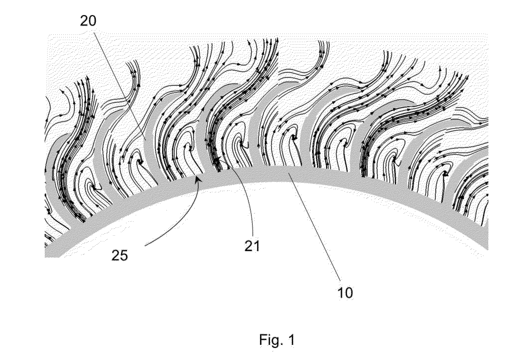
[0028]FIG. 1 shows a flow diagram of a drum rotor wheel 10 according to the state of the art. The blades 20 are curved forward with a pronounced curvature. The flow cannot follow the pronounced curvature and it becomes separated on the leading edge 21 of the blades 20, so that an area 25 of flow separation is formed, whereby eddy formation occurs in this area 25, resulting in losses due to dissipation.

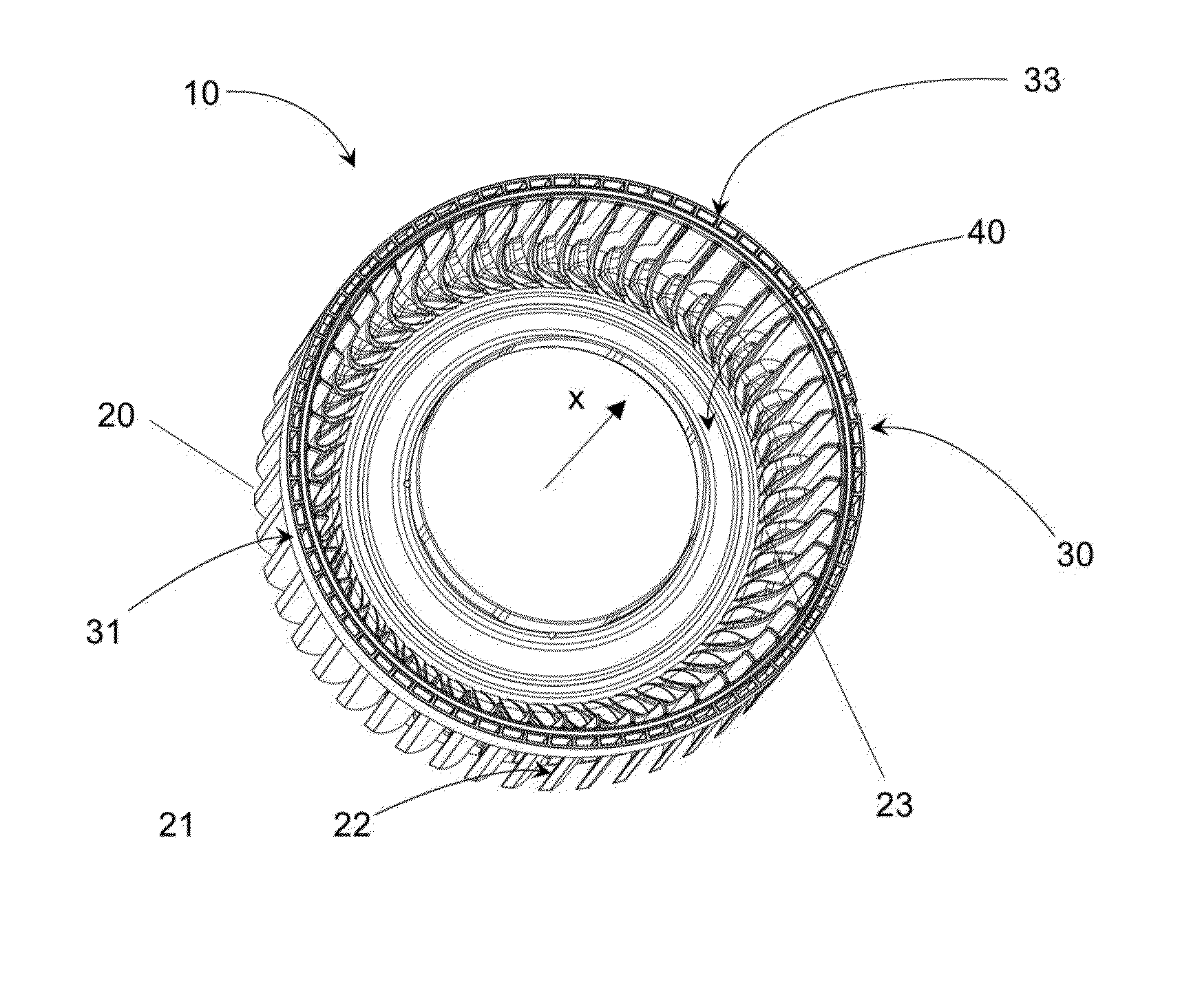
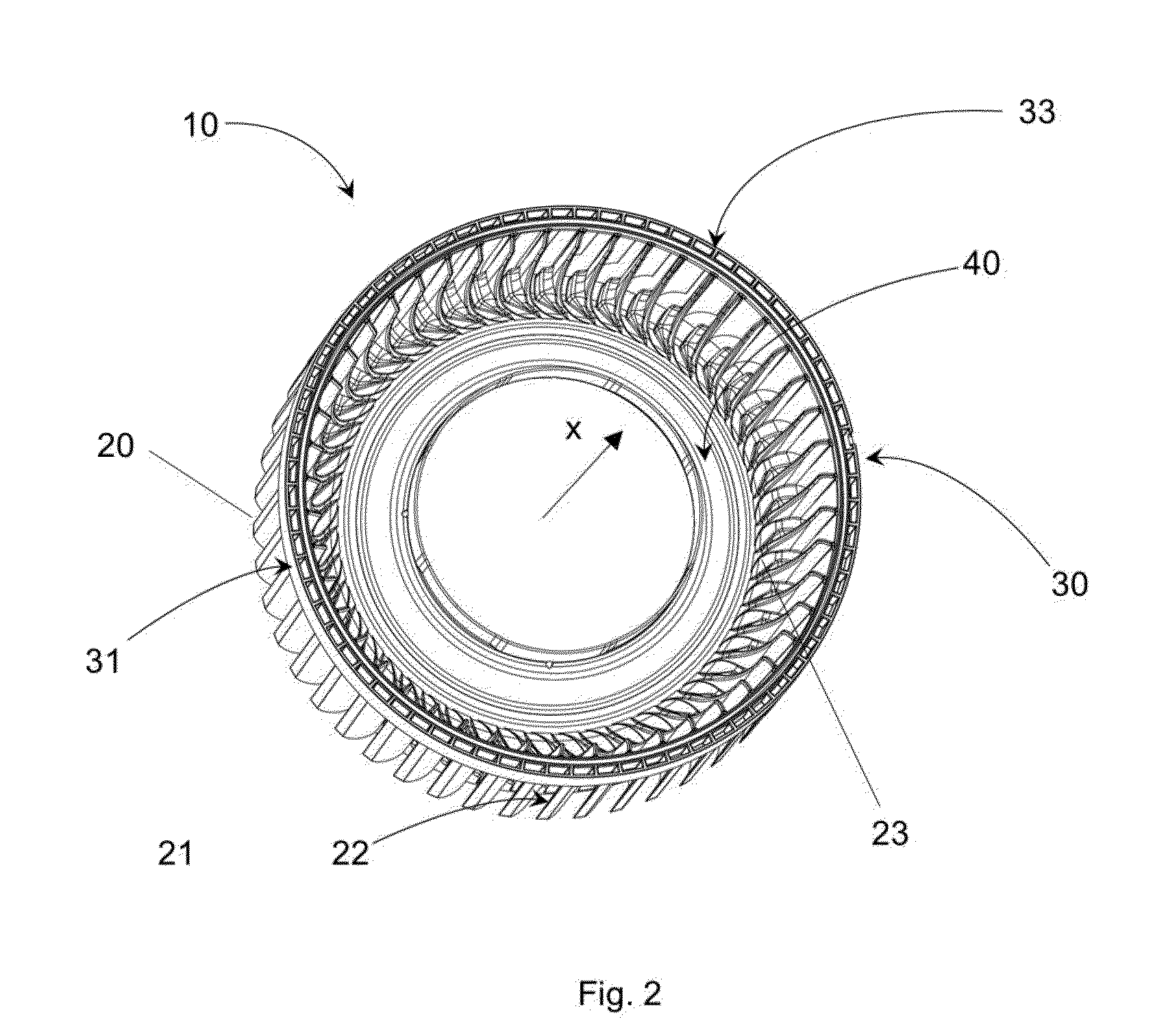
[0029]FIG. 2 shows a drum rotor wheel 10 according to the invention in a three-dimensional view as seen from the top disc 30. The drum rotor wheel 10 has numerous short blades 20 that are curved forward. The blades 20 have a leading edge 21 and a trailing edge 22. A top disc 30 and a bottom disc 40 are provided on the drum rotor wheel 10. The blades 20 of the drum rotor wheel 10 have bulges 23 on their leading edge 21. This bulge 23 minimizes the area 25 of flow separation on each blade 20 in FIG. 1, as a result of which the total extent of flow separation is likewise minimized. The bu...


PUM


Abstract

The invention relates to a drum rotor wheel for a fan having bulges to accommodate balancing weights. A drum rotor wheel according to the invention has several blades that are curved forward. The blades have a leading edge and a trailing edge. A top disc and a bottom disc are provided on the drum rotor wheel. At least one blade of the drum rotor wheel has a bulge on its leading edge. This bulge minimizes the area of flow separation, as a result of which the magnitude of the flow separation is likewise minimized. In other words, due to the bulge, the efficiency of the drum rotor wheel is increased.

Description

TECHNICAL FIELD[0001]The invention relates to a drum rotor wheel for a fan.BACKGROUND[0002]Drum rotor fans are radial flow machines with a rotor wheel that has numerous short blades that are curved forward. Thanks to the forward-curved blades, drum rotors reach operating points that are desirable in terms of the achievable flow rate and pressure increase in the flow medium at much lower rotational speeds than radial fans with blades that are curved backward, something that is desirable, for example, for use in air-conditioning systems. The forward curvature brings about a high level of energy transfer from the fan to the conveying fluid. Drum rotors are used with a housing that converts the high kinetic energy into pressure energy. The flow enters the fan axially, it is accelerated, and leaves the housing radially. The forward curvature of the blades is characterized by a strong flow deflection, whereby in most cases, the flow cannot follow the blade curvature, as a result of which ...

Claims


Application Information

Patent Timeline
Patent Type & Authority Applications(United States)
IPC IPC(8): F01D5/02
CPCF01D5/027F04D29/282F04D29/30F04D29/662F04D29/681F05D2240/306
Inventor HOFF, MARKUSBOHL, KATRINSTROHMEIER, REINHARD
Owner EBM PAPST MULFINGEN GMBH & CO KG
Why Eureka
Try Eureka