Modal decomposition of a laser beam

Inactive Publication Date: 2015-10-15
CSIR
View PDF8 Cites 17 Cited by
  • Summary
  • Abstract
  • Description
  • Claims
  • Application Information

AI Technical Summary

Benefits of technology

[0019]Preferably, step (c) is performed using digital holograms to implement the ma

Problems solved by technology

Despite the appropriateness of the techniques, the experiments to date are nevertheless rather complex or customised to analyse a very specific mode set.
Clearly this is a serious disadvantage if the t

Method used


Image

  • Modal decomposition of a laser beam
  • Modal decomposition of a laser beam
  • Modal decomposition of a laser beam

Examples


Embodiment Construction

[0034]Optical fields can be described by a suitable mode set; the spatial structure of this mode set {ψn(r)} can be derived from the scalar Helmholtz equation. Any arbitrary propagating field U(r) can be expressed as a phase dependent superposition of a finite number of nmax modes:

U(r)=∑n=1 nmaxcnψn(r)(1)

where due to their orthonormal property

(ψn|ψm)=∫∫R2d2rψ*n(r)ψm(r)=δnm,  (2)

the complex expansion coefficients cn may be uniquely determined from

cn=ρn exp(iΔφn)=(ψn|∪)  (3)

and are normalized according to

∑n=1 nmaxcn2=∑n=1 nmaxρn2=1(4)

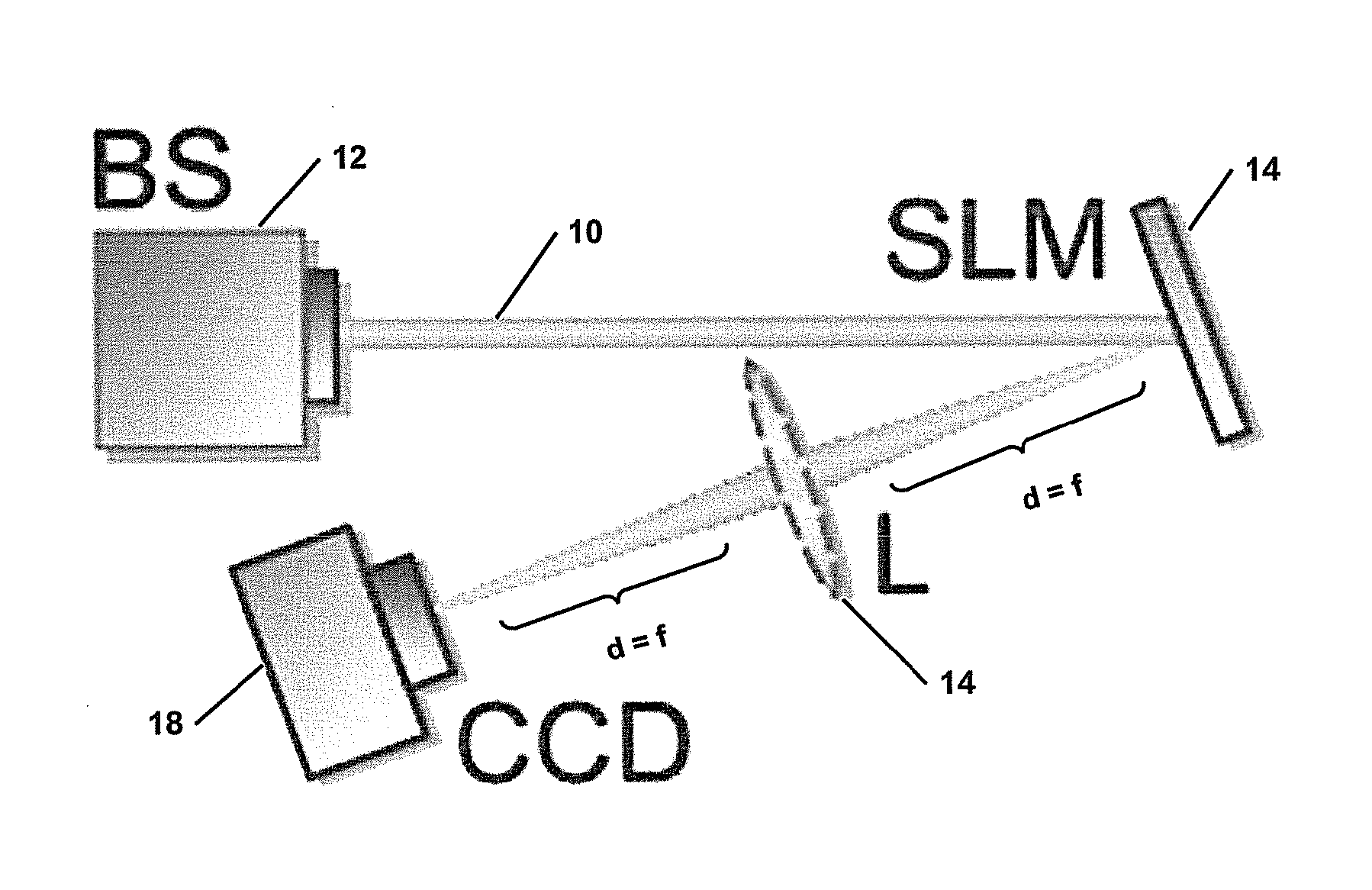
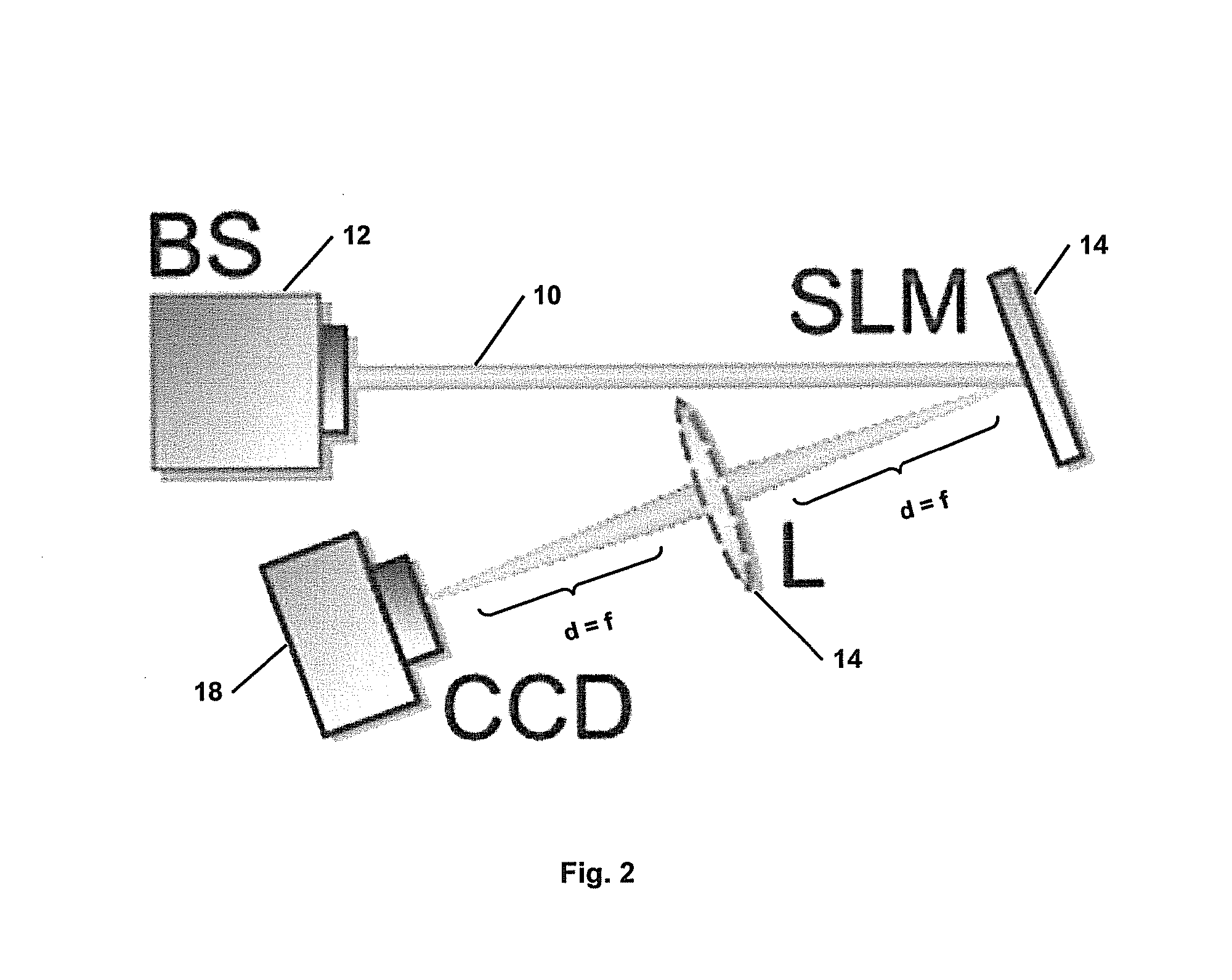
[0035]The benefit of this basis expansion of the field is that the required information to completely describe the optical field [Eq. (1)] is drastically reduced to merely nmax complex numbers: this is sufficient to characterize every possible field in amplitude and phase. A further benefit is that the unknown parameters in Eq. (3), the modal weights (ρ2n) and phases (Δφn) can be found experimentally with a simple optical set-up for an inner product measu...


PUM


Abstract

A method and apparatus for performing a modal decomposition of a laser beam are disclosed. The method includes the steps of performing a measurement to determine the second moment beam size (w) and beam propagation factor (M2) of the laser beam, and inferring the scale factor (wO) of the optimal basis set of the laser beam from the second moment beam size and the beam propagation factor, from the relationship: wO=w/M2. An optimal decomposition is performing using the scale factor wO to obtain an optimal mode set of adapted size. The apparatus includes a spatial light modulator arranged for complex amplitude modulation of an incident laser beam, and imaging means arranged to direct the incident laser beam onto the spatial light modulator. Fourier transforming lens is arranged to receive a laser beam reflected from the spatial light modulator. A detector is placed a distance of one focal length away from the Fourier transforming lens for monitoring a diffraction pattern of the laser beam reflected from the spatial light modulator and passing through the Fourier transforming lens. The apparatus performs an optical Fourier transform on the laser beam reflected from the spatial light modulator and determines the phases of unknown modes of the laser beam, to perform a modal decomposition of the laser beam.

Description

BACKGROUND TO THE INVENTION[0001]This invention relates to a method of performing a modal decomposition of a laser beam, and to apparatus for performing the method.[0002]The decomposition of an unknown light field into a superposition of orthonormal basis functions, so-called modes, has been known for a long time and has found various applications, most notably in pattern recognition and related fields [Reference 1], and is referred to as modal decomposition. There are clear advantages in executing such modal decomposition of superpositions (multimode) of laser beams, and several attempts have been made with varying degrees of success [References 2-6].[0003]To be specific, if the underlying modes that make up an optical field are known (together with their relative phases and amplitudes), then all the physical quantities associated with the field may be inferred, e.g., intensity, phase, wavefront, beam quality factor, Poynting vector and orbital angular momentum density. Despite the...

Claims


Application Information

Patent Timeline
IPC IPC(8): G01J1/42G01J9/00H01S3/00G01J1/04
CPCG01J1/4257G01J1/0437H01S3/0014G01J9/00G01J1/0411G01J1/0407G01J1/4228G01J2009/004H01S3/005H01S3/08054H01S3/0815H01S3/09415
Inventor FORBES, ANDREWSCHULZE, CHRISTIANDUPARRE, MICHAEL RUDOLFNGCOBO, SANDILE
Owner CSIR
Why Eureka
Try Eureka