
Battery controller, management system, battery control method, battery control program, and storage medium

a battery controller and management system technology, applied in the field of battery controllers, can solve the problem of not being able to efficiently control the power supplied to the equipment, and achieve the effect of efficient control of electric power

Active Publication Date: 2015-10-15
KK TOSHIBA
View PDF5 Cites 10 Cited by
  • Summary
  • Abstract
  • Description
  • Claims
  • Application Information

AI Technical Summary

Benefits of technology

The present invention provides a battery controller, a management system, a battery control method, a battery control program, and a storage medium that can efficiently control the electrical power supplied to equipment at or above the command value of the received power amount based on a demand response signal. This is achieved by a holder, calculator, acquirer, calculator, and controller working together to calculate the difference between the present value of the amount of received power and the last-held value, and to acquire a command value for each predetermined time period. The calculator then calculates a limit value for each time period, which the controller uses to control charge and discharge in the rechargeable battery. This allows for better management of power consumption and efficient use of the battery's energy.

Problems solved by technology

There are cases in which the battery controller, at or above a command value of received power amount included in the demand response signal, cannot efficiently control the power supplied to the equipment.

Method used


Image

  • Battery controller, management system, battery control method, battery control program, and storage medium
  • Battery controller, management system, battery control method, battery control program, and storage medium
  • Battery controller, management system, battery control method, battery control program, and storage medium

Examples


first embodiment

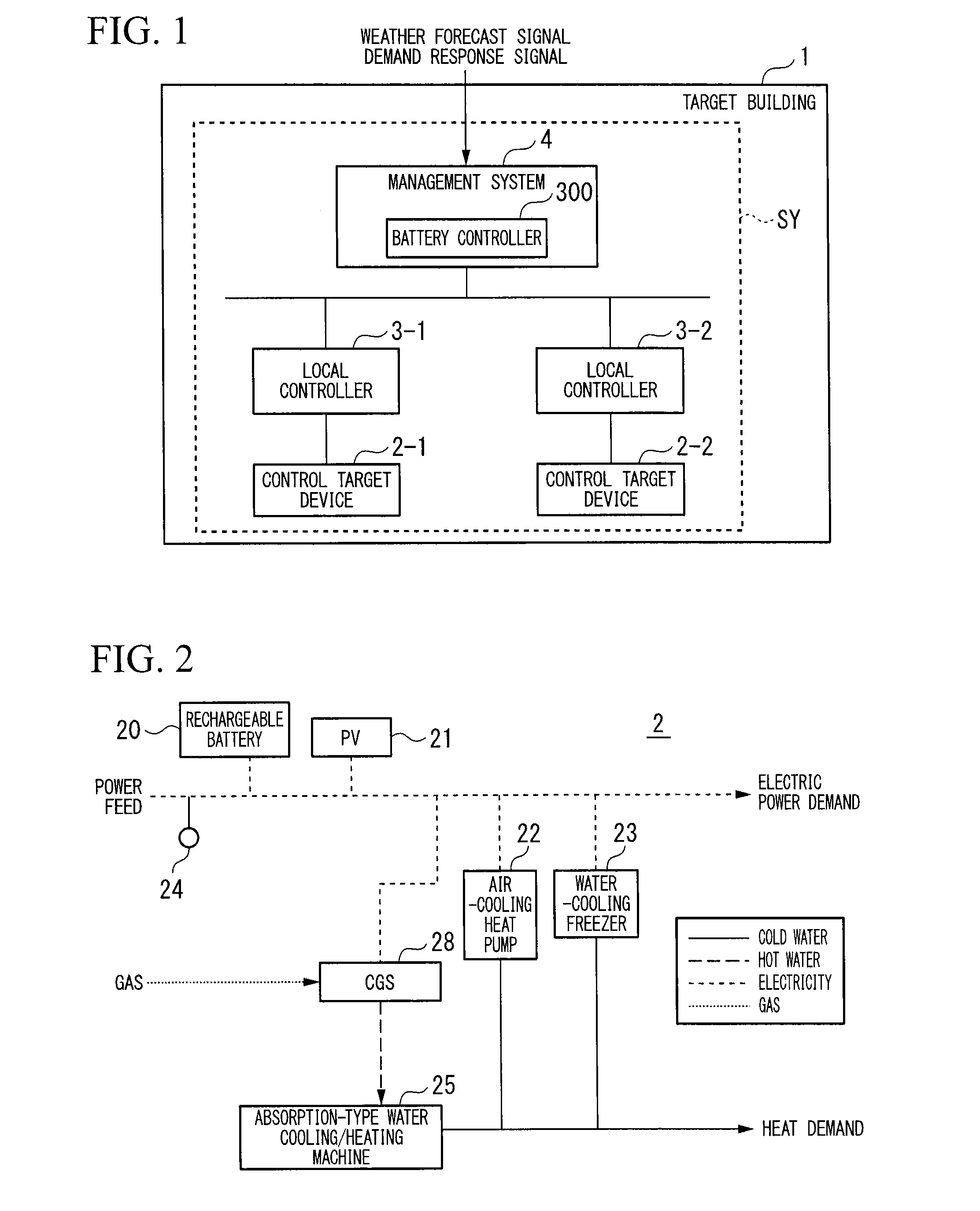
[0026]The battery controller controls charging and discharging of a rechargeable battery, based on a demand response (DR) signal, thereby enabling control of the electric power supplied to the controlled equipment from the rechargeable battery.

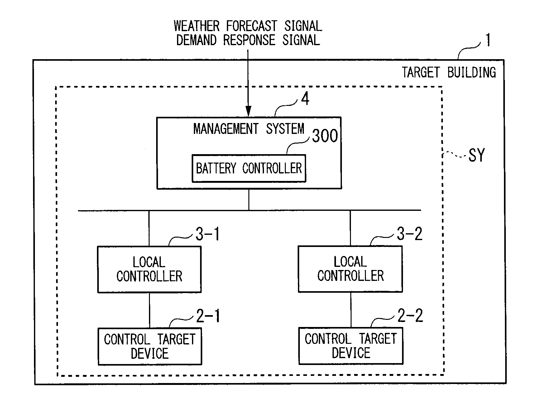
[0027]FIG. 1 shows a control system SY. The control system SY may be provided in the target building 1, or may be provided in a predetermined location outside the target building 1. The control system SY may be provided with distributed functional blocks. In the following, the description will continue as an example the control system SY being provided in the target building 1.

[0028]The control system SY has a control target device 2, a local controller 3, and a management system 4. There may be a plurality of control target devices 2. That is, the control system SY may have control target devices 2-1 to 2-n (where n is an integer of 2 or greater). The control system SY has the local controller 3, and may also have a plurality of local control...

second embodiment

[0111]In the second embodiment, the discharge of the rechargeable battery 20 is executed continuously immediately before the holding time, this being different from the first embodiment. In the following, only the differences with respect to the first embodiment will be described.

[0112]The charge and discharge of the rechargeable battery 20 is used in adjusting the received power amount supplied to the control target device 2 from the electrical power system. For this reason; the required electricity unit price for charging and discharging of the rechargeable battery 20 are the same as the received electricity unit price. Therefore, there are cases in which the rechargeable battery 20 is charged by a high electricity unit price in the peak time period during the day. For example, in the first embodiment, the item “charging cost during the DR time period” indicates that the charging cost of the rechargeable battery 20 in the third hour of the DR time period is “15,000 Yen” (refer to ...

third embodiment

[0141]In the third embodiment, the discharging of the rechargeable battery 20 so that the received power amount does not exceed the command value is the difference with respect to the second embodiment. In the following, only the differences with respect to the second embodiment will be described. In the third embodiment, the description assumes that the reverse current does not occur.

[0142]The received power meter 24 detects the received power amount supplied to the control target device 2 from the electrical power system over a predetermined time by accumulating a value of electric power supplied to the control target device 2 from the electrical power system over a predetermined time.

[0143]FIG. 15 shows the limit values of the received power amount, in which the horizontal axis represents time and the vertical axis represents the received power amount (kWh). The variation of the received power (kWh) supplied to the control target device 2 from the electrical power system from the...


PUM


Abstract

A battery controller has a holder, a calculator, an acquirer, a calculator, and a controller. The holder holds, at a predetermined time, a value of a received power supplied from an electrical power receiving system to equipment supplied with power from a rechargeable battery. A calculator calculates a difference between a present value of the received power and a last-held value of the received power last-held by the holder at the predetermined time. An acquirer acquires a command value of the received power for each predetermined time period defined by a predetermined time interval. A calculator calculates a limit value of the received power for each time that is shorter than the predetermined time, based on the command value of the received power for each predetermined time period. A controller controls charge and discharge in the rechargeable battery, based on the calculated difference and on the limit value.

Description

TECHNICAL FIELD[0001]Embodiments of the present invention relates to a battery controller, a management system, a battery control method, a battery control program, and a storage medium.BACKGROUND ART[0002]Of the electrical energy consumed in facilities such as buildings, it is said that the consumed amount thereof in the private business sector such as commercial facilities accounts for approximately 20% of all facilities, a non-negligible amount of energy. With the tight supply-and-demand situation in recent years, there are cases in which large-scale consumers of electric power are subjected to upper limitations on the demand for received power amount (received electric power amount) to equipment (power consumer equipment), by reductions of power supplied during peak demand hours along and an increased demand to shift the peak-time by making use of heat-accumulators.[0003]With the foregoing as a backdrop, the adoption of PV (photovoltaic), wind power, and solar heat equipment and...

Claims


Application Information

Patent Timeline
Patent Type & Authority Applications(United States)
IPC IPC(8): H02J7/00
CPCH02J7/007H02J3/008H02J7/0068H02J2310/14H02J2207/10H02J3/32H02J7/0047H02J7/35Y02B70/3225Y04S20/222Y02P90/50H02J3/003H02J2310/12H02J3/14H02J3/00H02J3/38H02J7/00H02J7/04
Inventor MURAYAMA, DAISAITO, MASAAKIHISADA, NAGAKOIINO, YUTAKA
Owner KK TOSHIBA
Learn More