
Split piston metering pump

Active Publication Date: 2015-10-22
BECTON DICKINSON & CO
View PDF5 Cites 23 Cited by
  • Summary
  • Abstract
  • Description
  • Claims
  • Application Information

AI Technical Summary

Benefits of technology

The invention is a piston arrangement for a hydraulic power source. In the fourth embodiment, a gear engages the drive rack through an opening in the pump housing, which makes the piston arrangement shorter and reduces the overall size of the power source.

Problems solved by technology

However, these embodiments are relatively complex and not cost effective.
Thus, it is impossible to use a flexible reservoir and the number of possible layouts for the pump is consequently limited.

Method used


Image

  • Split piston metering pump
  • Split piston metering pump
  • Split piston metering pump

Examples


third embodiment

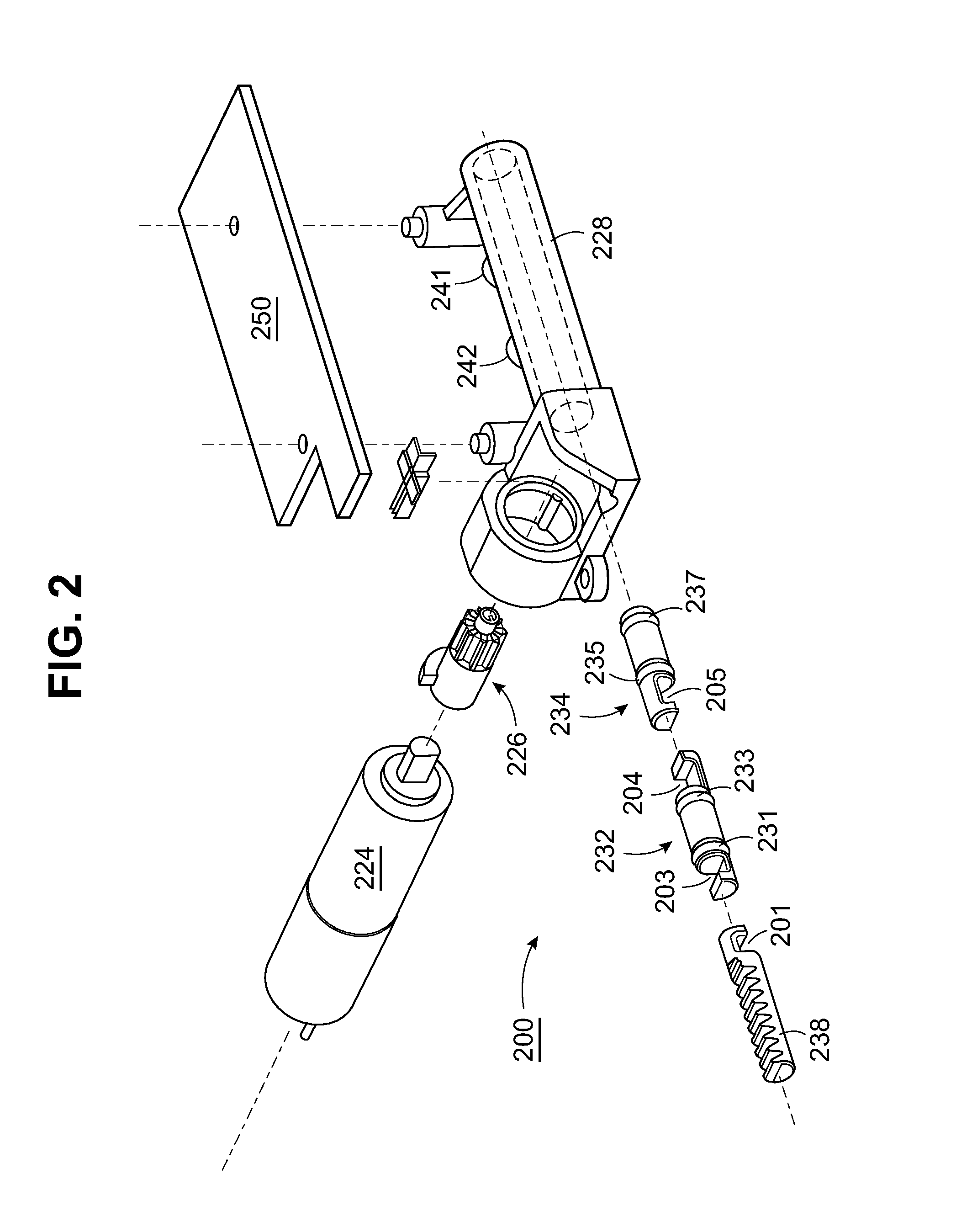
[0071] as seen in the exploded view of FIG. 21, motor 424 is received in a housing 425, which may be integral with a tubular pump housing 438. As in the preceding embodiments, pinion gear 426 engages a drive rack 428 which is coupled to a drive piston 432. The coupling of drive rack 428 to drive piston 432, as well as the engagement of drive piston 432 in spool 434 may take various forms. In the specific embodiment of FIG. 21, drive piston 432 remains inside the bore of spool 434 during the pump cycle, and drive rack 428 includes an axial extension 408 which couples to drive piston 432 using cooperating hooks 401, 402, which are also received in pump housing 438. Drive piston 432 is coupled to spool 434 using a coupling pin 403 received in slot 405 in spool 434 and through a hole 404 in the drive piston. The axial length of slot 405 and the diameter of coupling pin 403 determine the freedom of movement of drive piston 432 inside the bore of spool 434 during the pump cycle.

[0072]FIG....

fourth embodiment

[0077]In the invention, depicted in FIGS. 30 through 40B, the drive rack and piston are combined into one driven piston 501 which remains entirely within the floating piston bore throughout the pump cycle. A window 504 is cut into the side of the floating piston 534 to allow gear 526 to engage driven piston 501 received inside the pump housing and move it axially. This arrangement permits a shorter axial length for pump housing 538 and a smaller overall footprint.

[0078]In the assembled view of FIG. 31, pump housing 538 is shown formed with a housing 525 to receive the motor 524 and a support 502 for the pinion gear 526, so that the gear can access the drive rack portion of driven piston 501 through opening 504 in the floating piston 534.

[0079]The pump cycle for the fourth embodiment is similar to the pump cycle for the previous embodiment. In the extended position of FIG. 33A, the combined drive rack / piston 501 is fully extended into the bore of the floating piston 534, and the floa...


PUM


Abstract

A micropump according to the invention uses axially oriented pistons to define a pump volume. Translating the pistons axially with respect to each other within a pump housing draws a metered amount of fluid into the pump volume from a reservoir port for delivery to a cannula port when the space is collapsed. Radially situated seals on the pistons cooperate with the axial movement to close off and open the cannula port and the reservoir port respectively at different positions of the piston stroke.

Description

BACKGROUND OF THE INVENTION[0001]1. Field of the Invention[0002]The present invention is directed to a micropump adapted for the continuous delivery of a liquid medication by infusion such as may be used in the delivery of insulin for the treatment of diabetes.[0003]2. Description of the Related Art[0004]Micropumps for subcutaneous delivery of drugs are known, for example, from U.S. Pat. Nos. 7,726,955 and 8,282,366. This prior art describes, in various embodiments, a pump having a rotor mounted in a stator, or housing. Sealing rings situated at an angle on axial extensions on the rotor cooperate with channels formed between the rotor and the stator to move liquid in precise amounts through a rotor housing. However, these embodiments are relatively complex and not cost effective. The user keeps the pump when the infusion patch is changed for several weeks. As the art continues to evolve toward fully disposable pumps, the need for compact and economical micropump designs remains acut...

Claims


Application Information

Patent Timeline
IPC IPC(8): A61M5/142
CPCA61M5/142A61M5/14216A61M5/1422
Inventor FOCHT, KENNETHGORDON, JOSEPHPERRY, MATTHEW J.FISK, JUSTIN
Owner BECTON DICKINSON & CO
Features
  • Generate Ideas
  • Intellectual Property
  • Life Sciences
  • Materials
  • Tech Scout
  • Unparalleled Data Quality
  • Higher Quality Content
  • 60% Fewer Hallucinations
Learn More