Floating platform

a floating platform and platform technology, applied in the field of floating platforms, can solve the problems of reducing the efficiency of solar power plants carried thereon, and achieve the effects of limiting over-pressure, and reducing the number of floating platforms

Active Publication Date: 2015-10-22
VIENNA UNIVERSITY OF TECHNOLOGY
View PDF13 Cites 3 Cited by
  • Summary
  • Abstract
  • Description
  • Claims
  • Application Information

AI Technical Summary

Benefits of technology

[0011]By providing several buoyancy bodies separated from each other, which can be filled with pressurized air, lateral pressure exerted by approaching waves or wind cannot be transmitted from one buoyancy body to the next, as it is the case when simple divisions by partition walls are provided. In addition, the individual buoyancy bodies collectively counteract tilting of the platform: when the platform is tilted due to an external load or any other interference with the balance. The elevation of one side, as caused by the tilting, should increase the volume of the hollow space of the buoyancy bodies at this side. Due to the gas-tightness, however, the air pressure in this hollow space is reduced and thus counteracts the elevation. When tilting occurs, the pressure in the hollow spaces at the opposite side is simultaneously increased due to the immersion of the buoyancy bodies, which also counteracts tilting. The different pressures arising in the various chambers thus provide the platform with floating stability. In this manner, not even high waves or strong wind can tilt the inventive platform to a considerable extent. Even though another advantage of the invention is that the entire platform can be constructed of lightweight components.
[0012]However, desired tilting of the platform, particularly for orienting solar collectors or the like carried thereon according to the position of the sun, is definitely possible by setting different pressures in buoyancy bodies at opposite sides of the platform.
[0013]The material of the buoyancy bodies is not particularly limited, and plastic foils may for example be used. Preferably, membranes made of fiber-reinforces plastics are used in order to provide the required flexibility as well as sufficient pressure resistance and tensile strength and, at the same time, to ensure that expansibility is limited in the pressurized state. Thus, foils can be based on PVC, polypropylene or ABS (acrylonitrile butadiene styrene copolymers). Preferred are seawater and UV resistant plastics, such as ethylene tetrafluoroethylene (ETFE) copolymers, which may all contain corresponding stabilizers.
[0014]The minimum number of inventive buoyancy bodies of three results from the effect described above. Only with three buoyancy bodies or more, which are arranged offset, i.e. not in a straight line, preferably being offset to each other by 120°, around the center of gravity of the platform, the above restoring force against tilting, which results from potential under- and over-pressures in the hollow spaces, can unfold. Generally, this is the reason why preferred embodiments of the present invention have three or more buoyancy bodies symmetrically arranged around the center of gravity of the platform. In some preferred embodiments, the cover element is square, and four or nine buoyancy bodies are symmetrically arranged around its center. Or any number larger than 3 can be arranged in a circular, cross-shaped or star-shaped manner around the center of gravity.
[0015]The relation between the sum total of the cross-sectional areas or the hollow space volumes of the buoyancy bodies and the surface of the cover element is not specifically limited as long as the volume of the hollow spaces enclosed by the buoyancy bodies is sufficient to provide the entire floating platform including the load carried thereon, e.g. a solar power plant, with the required buoyancy. Preferably, the sum total of the cross-sectional areas of the buoyancy bodies is at least half of the area of the cover element in order to limit the over-pressure in the buoyancy bodies.
[0016]When the relation between the sum total of the cross-sectional areas of the buoyancy bodies and the surface of the cover element is relatively small, the buoyancy bodies are preferably attached at the edges of the platform in order to avoid tilting.

Problems solved by technology

The main disadvantage of the embodiments according to the state of the art is that the individual floating platforms are not sufficiently protected against tilting due to waves, which reduces the efficiency of solar power plants carried thereon.

Method used


Image

  • Floating platform
  • Floating platform
  • Floating platform

Examples


Embodiment Construction

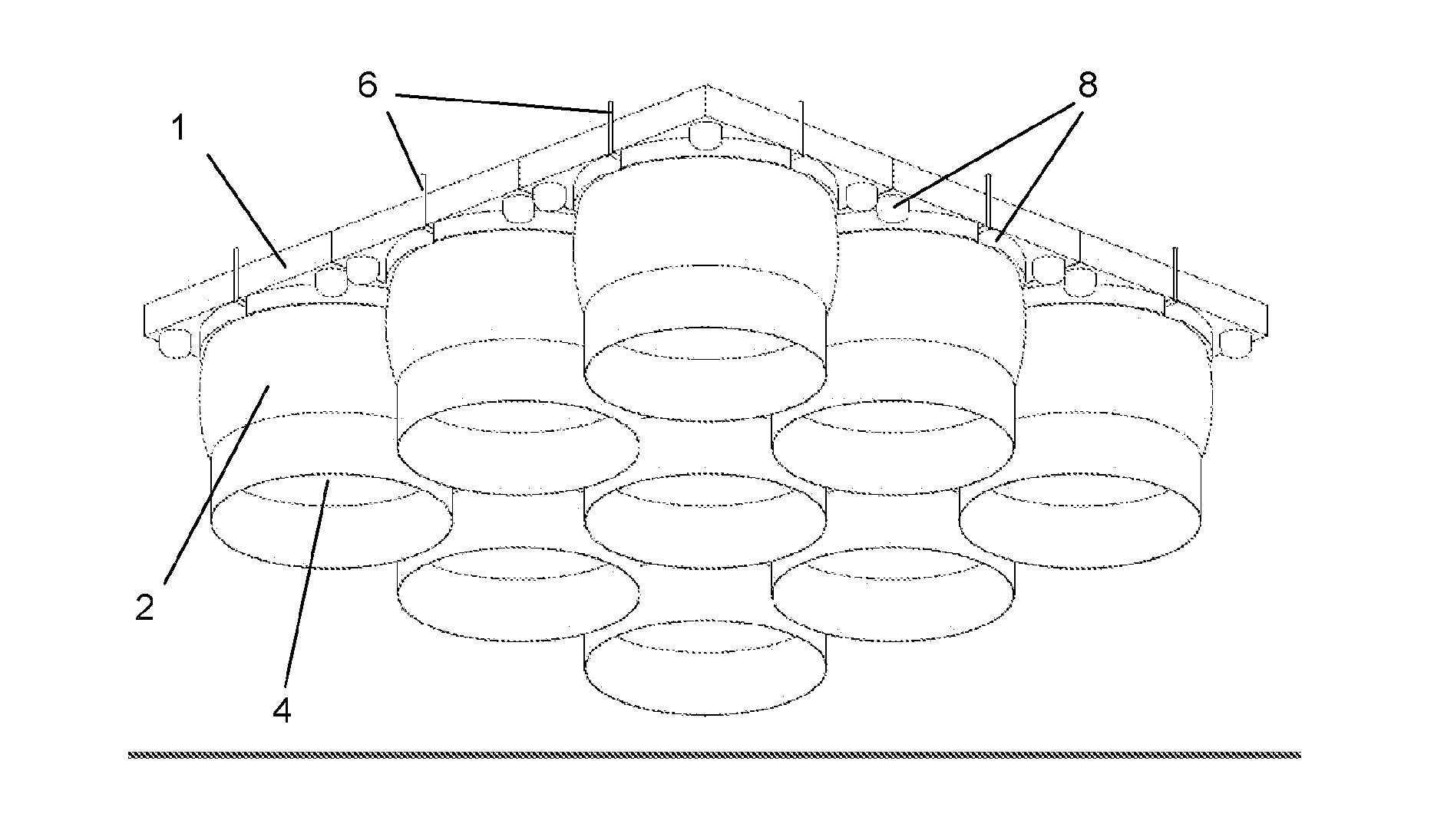
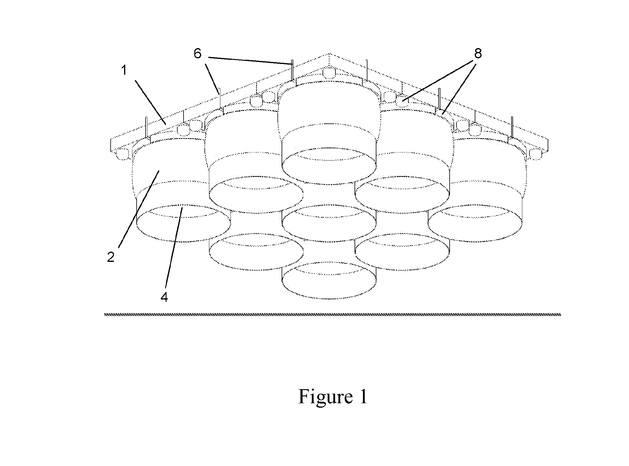
[0038]FIG. 1 shows a preferred embodiment of the inventive floating platform in an isometric, slanted view from below. The cover element 1, here shown to be continuous, has a square shape. At its bottom side, nine buoyancy bodies 2 are arranged symmetrically around the square (one right in the center of gravity), the cross-sectional areas of which together cover most of the area of the cover element 1.

[0039]Each buoyancy body 2 has (in its pressurized state) a cross-sectional shape that substantially corresponds to an upside-down U profile, the cross section of which is tapered downwards and which, together with the water surface (not shown), defines a hollow space 4. The reference number 6 marks air suction lines leading to pumps (not shown) and from there to the individual buoyancy bodies. Next to the buoyancy bodies and around them, additional closed floating bodies 8 are provided. The latter each have the shape of circular ring segments, as this is better shown in the Figures de...


PUM


Abstract

A floating platform is provided including the following: a covering element; at least three buoyant bodies, which are separated from each other, are fixedly mounted to the lower face of the covering element, are open toward the bottom, and are made of a gas-tight, pressure- and corrosion-resistant flexible material. The buoyant bodies enclose a closed hollow space when coming into contact with a liquid surface. At least one compressed-air generating device is also provided for generating an overpressure in the individual hollow spaces.

Description

CROSS-REFERENCE TO RELATED APPLICATIONS[0001]This application is a Section 371 of International Application No. PCT / AT2012 / 050096, filed Jul. 9, 2012, which was published in the German language on Jan. 17, 2013, under International Publication No. WO 2013 / 006881 A. and the disclosure of which is incorporated herein by reference.BACKGROUND OF THE INVENTION[0002]The invention relates to a floating platform, in particular for plants for the production of solar energy.[0003]The production of so-called alternative energy, in particular of solar energy, has been continuously rising. Due to the relatively large space required for solar power plants, the aim is to transfer them to water surfaces, in particular of the oceans (“offshore solar power plants”). Recently, various floating platforms have been developed for this purpose to carry the respective plants. Because of the requirements of a simple and lightweight design with at the same time high load capacity, the newest platforms develo...

Claims


Application Information

Patent Timeline
Patent Type & Authority Applications(United States)
IPC IPC(8): B63B35/44B63B39/03F24J2/52B63B3/08
CPCB63B35/44B63B3/08B63B2035/4453F24J2/5267B63B39/03F24S20/70F24S30/422Y02E10/47
Inventor HAIDER, MARKUSRAMMERSTORFER, FRANZBOHM, HELMUTDIENDORFER, CHRISTIANTOTH, FLORIAN
Owner VIENNA UNIVERSITY OF TECHNOLOGY
Why Eureka
Try Eureka