An airframe leading edge
a leading edge and airframe technology, applied in the field of airframe leading edge, can solve the problems of high risk of accident, collisions may occur, and heavy birds could damage the structure of the wing/fin/stabilizer/nacelle/nose, so as to save time and cost, save damage, and cost-effectively replace the
- Summary
- Abstract
- Description
- Claims
- Application Information
AI Technical Summary
Benefits of technology
Problems solved by technology
Method used
Image
Examples
first embodiment
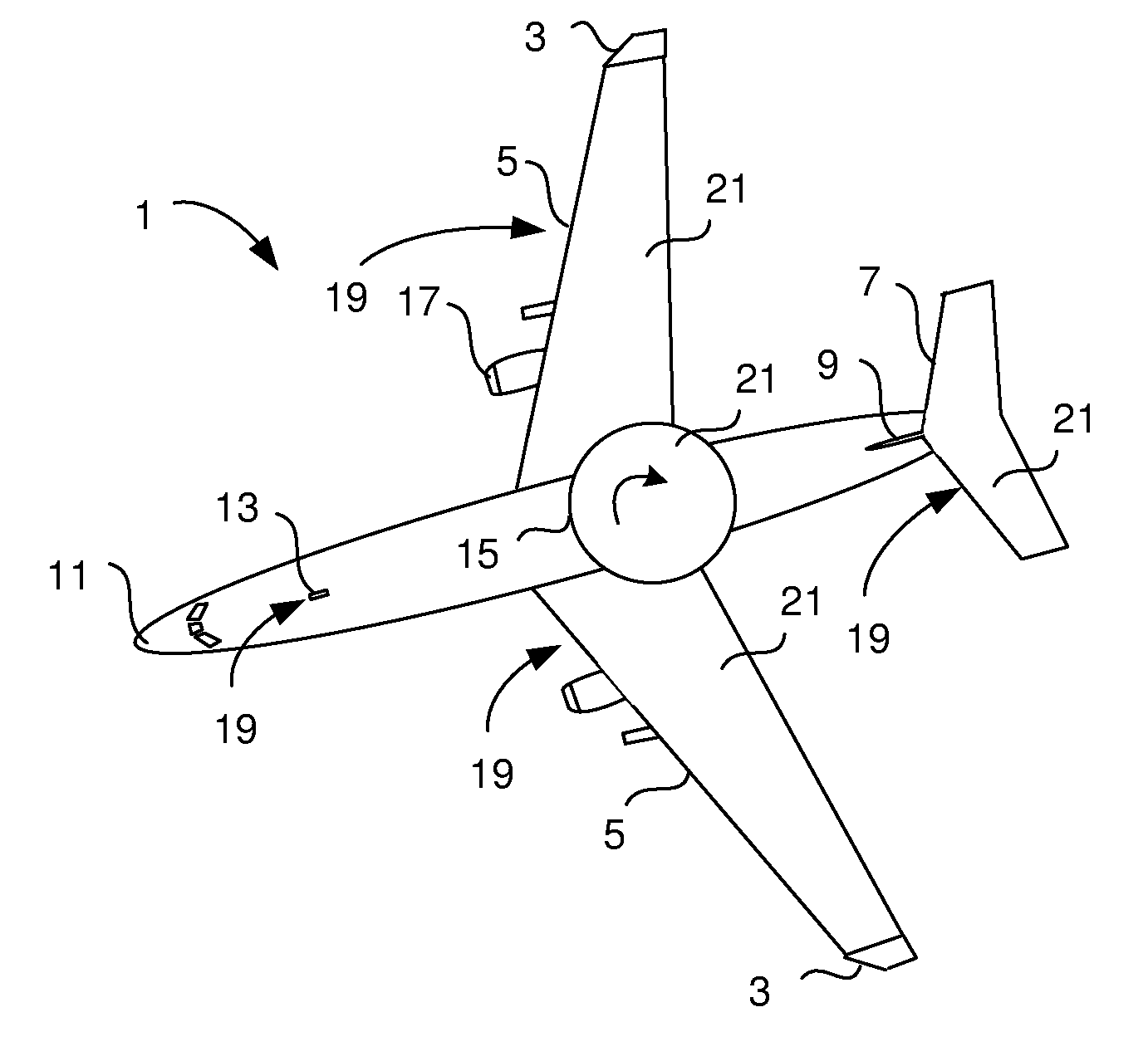
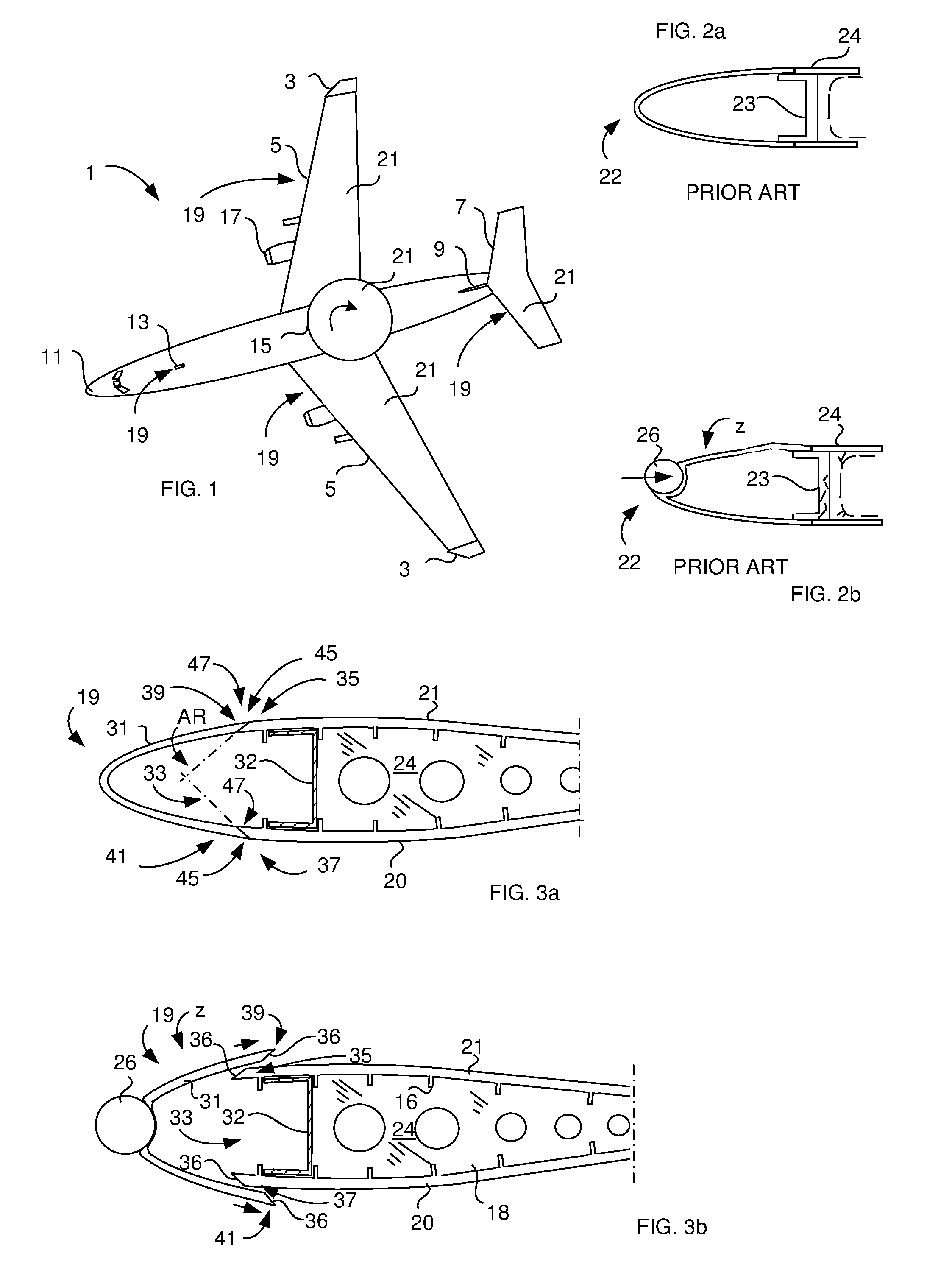
[0089]FIGS. 3a and 3b illustrate a cross-sectional view of an airframe leading edge part 19 comprising a leading edge skin 31 according to the present invention. The airframe leading edge part 19 is formed as a U-formed profile and is designed to be replaceable (removable) fixed to an upper 35 and lower 37 wing skin edge of a wing skin 20, 21 (lower and upper skin), which during use moves through the air. The wing skins 20, 21 are parts of a structural portion 33 comprising a U-beam 32, wing ribs 18 and stringers 16, all of which parts are constituting a so called wing box 24 of the wing. The airframe leading edge part 19 comprises a first 39 and a second 41 longitudinal joint edge, each of which is adapted to fit the respective wing skin edge 35, 37. The respective fit is made by joining each longitudinal joint edge 39, 41 to said corresponding wing skin edge 35, 37 via an adhesive 45 forming a joint 47 between the wing skin edge 35, 37 and said longitudinal joint edge 39, 41. The ...
second embodiment
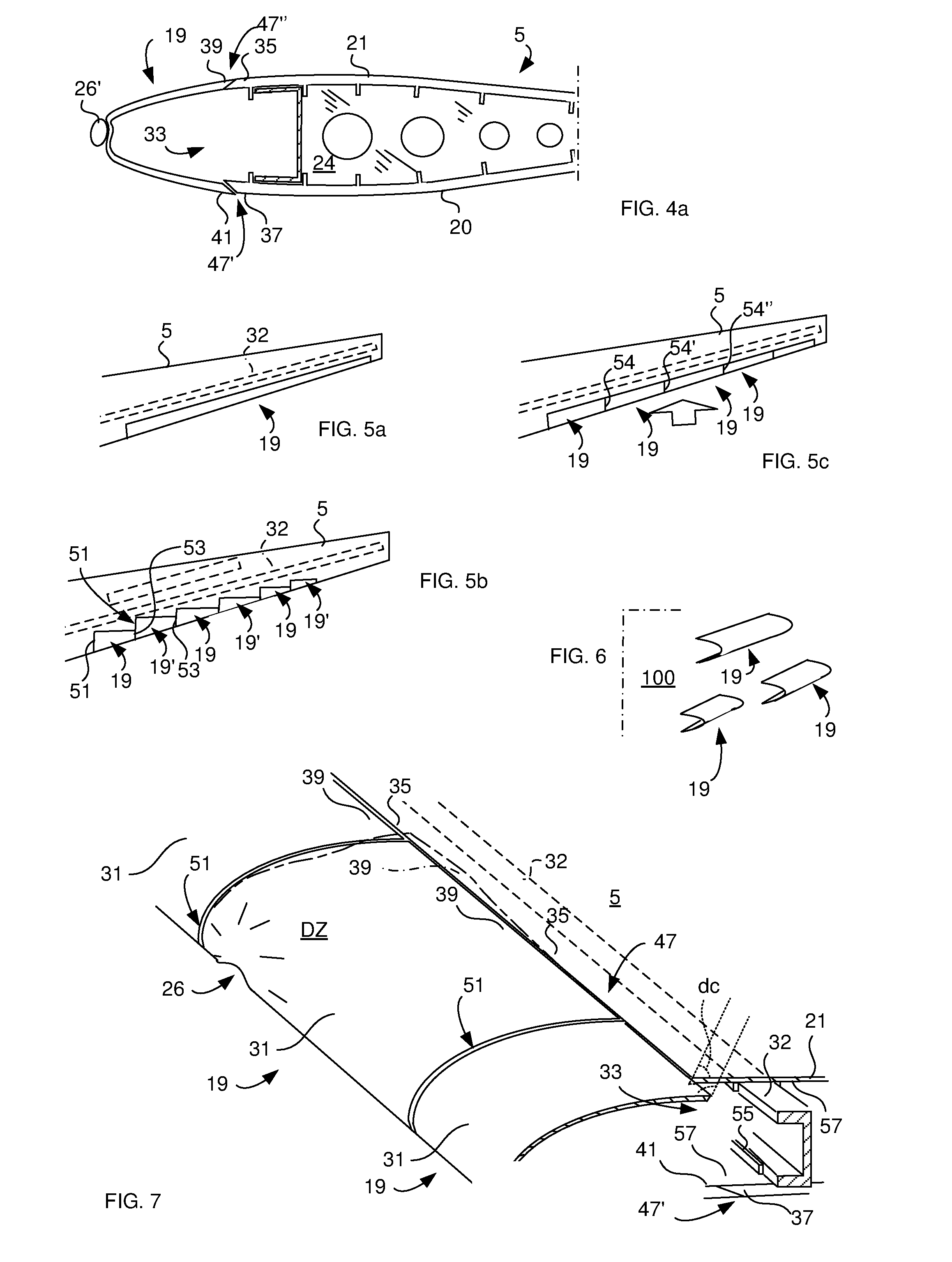
[0091]FIG. 4a schematically illustrates a cross-sectional view of an airframe leading edge part 19 according to a Only one joint (the lower 47′) is adapted to break in the event of foreign object 26′ impact. The joint 47′ is designed to break at a beforehand determined maximum joint strength (Pmax) of the joint's 47′ adhesive 45 (bonding together the wing skin edge 37 and joint edge 41 during normal use of the airframe) for protecting the wing box 24 and other structural wing parts, such as lower 20 and upper 21 skins of the wing 5, from breakage in case of said impact. The upper joint 47″ is firmly adhered to the structural portion's 33 upper wing skin edge 35 of the upper wing skin 21.
[0092]FIG. 4b schematically illustrates a portion of a leading edge part 19 mounted to a structural portion 33 including an upper composite skin 35. The leading edge part is made of metal and is bolted (bolts 14) to the skin 35. The area of the longitudinal joint edge comprises an outermost edge sec...
third embodiment
[0098]FIG. 5a schematically illustrates a wing 5 comprising an airframe leading edge part 19 being designed according to a The airframe leading edge part 19 is made in one piece for covering the wing's 5 edge facing the airflow.
PUM
| Property | Measurement | Unit |
|---|---|---|
| angle | aaaaa | aaaaa |
| angle | aaaaa | aaaaa |
| thickness | aaaaa | aaaaa |
Abstract
Description
Claims
Application Information
 - R&D
- Intellectual Property
- Life Sciences
- Materials
- Tech Scout
- Unparalleled Data Quality
- Higher Quality Content
- 60% Fewer Hallucinations
Browse by: Latest US Patents, China's latest patents, Technical Efficacy Thesaurus, Application Domain, Technology Topic, Popular Technical Reports.
© 2025 PatSnap. All rights reserved.Legal|Privacy policy|Modern Slavery Act Transparency Statement|Sitemap|About US| Contact US: help@patsnap.com


