
Wind power installation and method for injecting electrical energy

a technology of wind power and electrical energy, applied in the direction of electric generator control, machine/engine, dynamo-electric converter control, etc., can solve the problems of insufficient reach, loss or at least weakened balancing effects of former injecting generators, and increasing replacement of large-scale generators with other injection units. to achieve the effect of enhancing—grid quality

Active Publication Date: 2015-10-22
WOBBEN PROPERTIES GMBH
View PDF2 Cites 5 Cited by
  • Summary
  • Abstract
  • Description
  • Claims
  • Application Information

AI Technical Summary

Benefits of technology

The proposed method includes checking the grid for an asymmetrical system incident and injecting a symmetrical system if an asymmetrical incident is not detected. This helps to maintain the quality of the grid during normal operation.

Problems solved by technology

This means that such large-scale generators are being increasingly replaced with other injection units, such as cyclo-inverters.
The main concerns are that the possible balancing effects of the former injecting generators might be lost or at least weakened with an increasing degree of substitution.
Initial objectives do exist, but they may not be reaching far enough.

Method used


Image

  • Wind power installation and method for injecting electrical energy
  • Wind power installation and method for injecting electrical energy
  • Wind power installation and method for injecting electrical energy

Examples


Embodiment Construction

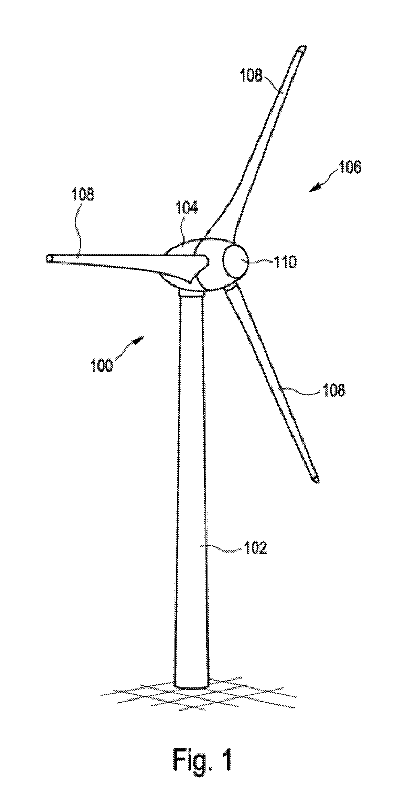
[0029]FIG. 1 shows a wind power installation 100 with a tower 102 and a nacelle 104. A rotor 106 with three rotor blades 108 and a spinner 110 is located on the nacelle 104. When in operation, the rotor 106 is set into rotation by the wind and thereby drives a generator in the nacelle 104.

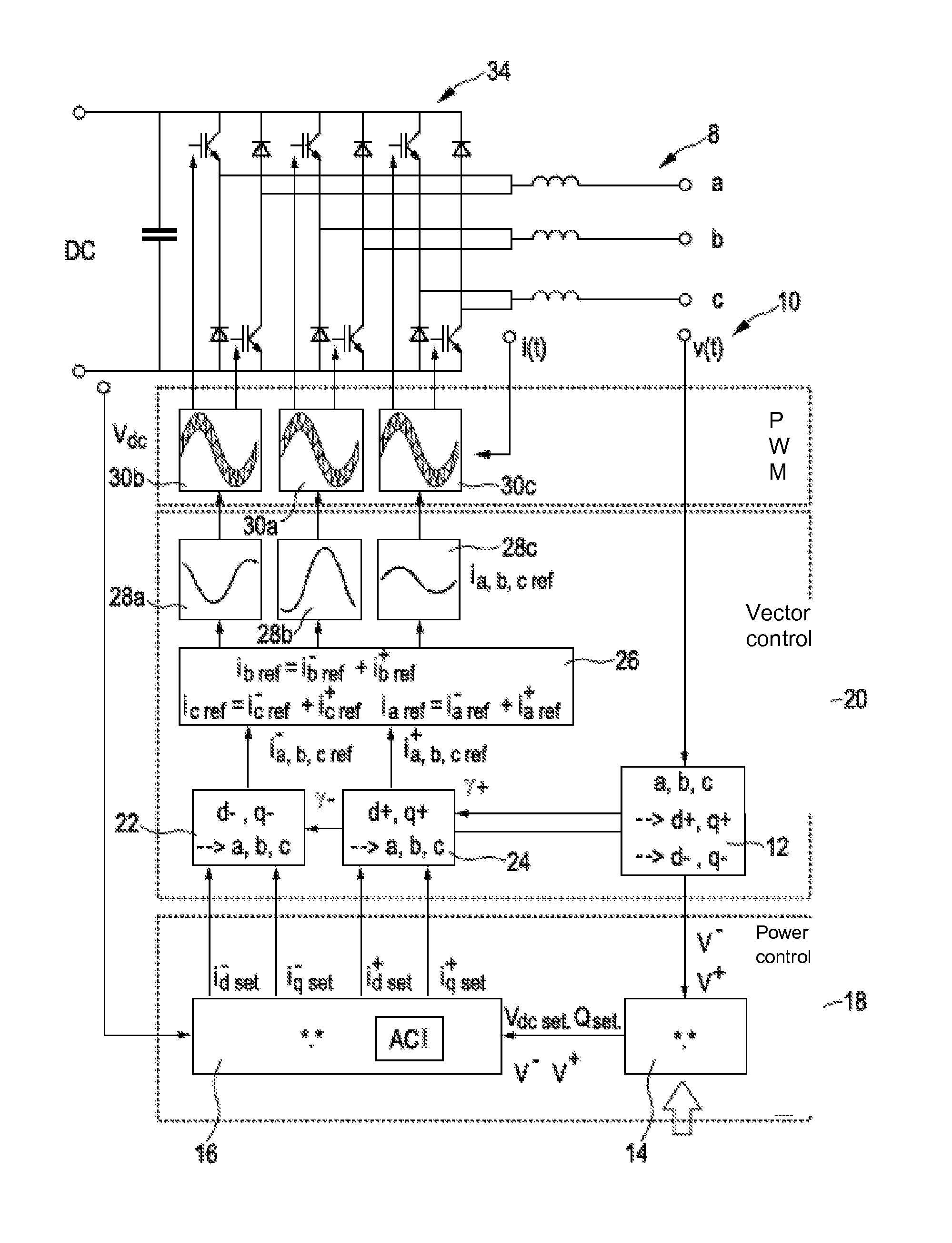
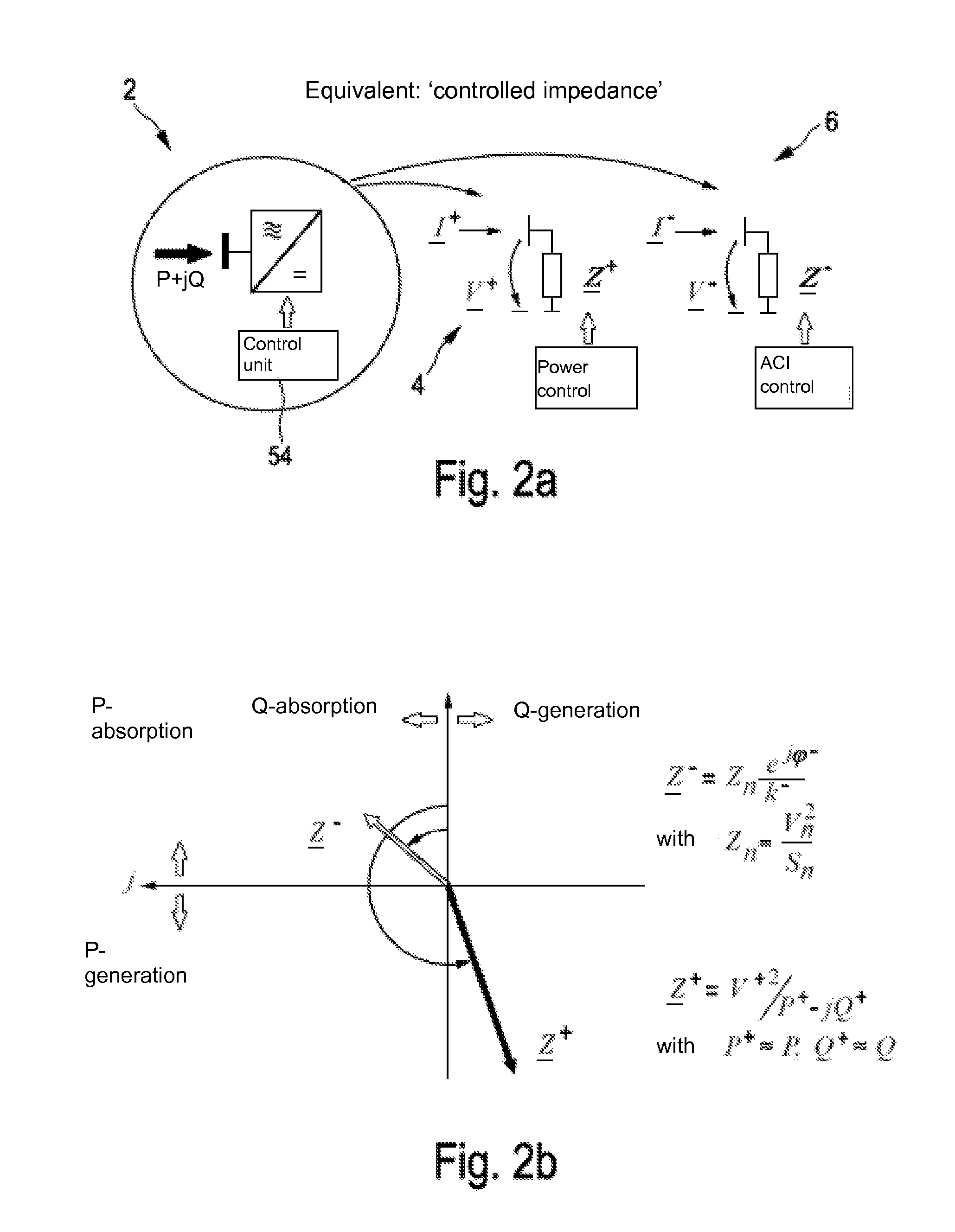
[0030]The following is explained with reference to FIGS. 2a, 2b and 2c.

[0031]The fundamental frequency content of voltages (and currents) is represented via phasors in symmetrical components

va=√{square root over (2)}Va cos(2πft+φVa)Va=VaejφVa

vb=√{square root over (2)}Vb cos(2πft+φVb)Vb=VbejφVb

vc=√{square root over (2)}Vc cos(2πft+φVc)Vc=VcejφVc

and transformed as usual:

V_0V_+V_-=131111j23πj43π1j43πj23πV_aV_bV_c

[0032]The unbalancing level used as a metric for unbalancing is given by the ratio of the magnitudes of the negative respective zero and positive sequence phasor:

V— / V+ respectively V0 / V+

[0033]Grid connected inverters can be interpreted by typical (time and state dependent) equivalents with...


PUM


Abstract

The present invention relates to a method for injecting electrical energy into an electrical, three-phase grid, comprising the steps of: injecting current by means of an injection unit at a grid connection point, detecting an asymmetry in the grid, in particular a negative sequence component in the grid, injecting an asymmetrical current portion into the grid for, at least, partial compensation of the detected asymmetry, with injection of the asymmetrical current portion taking place such that the injection unit behaves like a consumer.

Description

BACKGROUND[0001]1. Technical Field[0002]The present invention relates to a method for injecting electrical energy and a device, in particular a wind power installation, for injecting the electrical energy.[0003]2. Description of the Related Art[0004]Nowadays, electric grids, which may be hereinafter also simply referred to as electric nets or electric networks, are increasingly supplied by regenerative sources of energy, such as wind power installations or wind farms exhibiting a different electrical behavior than common large-scale power plants, which employ at least one large-scale generator for injecting current. This means that such large-scale generators are being increasingly replaced with other injection units, such as cyclo-inverters. This is also referred to by experts as substitution. Countries like Germany, in particular, have a comparatively high degree of substitution, which means that comparatively many generators are replaced with other injection units. This may also ...

Claims


Application Information

Patent Timeline
Patent Type & Authority Applications(United States)
IPC IPC(8): F03D9/00H02J3/50H02J3/18
CPCF03D9/003H02J3/50H02J3/18Y02E40/50H02J2300/28H02J3/381H02J3/48F03D9/255Y02E10/76Y02E10/72H02J3/26H02H9/00F03D7/0284
Inventor DIEDRICHS, VOLKER
Owner WOBBEN PROPERTIES GMBH
Learn More