System and method for a gas turbine engine

a gas turbine engine and gas turbine technology, applied in the direction of engines, efficient propulsion technologies, mechanical equipment, etc., can solve the problems of gas turbine engines typically consuming a vast amount of air, wasting exhaust gas, and releasing a considerable amount of exhaust gas into the atmospher

Active Publication Date: 2015-10-29
GENERAL ELECTRIC CO +1
View PDF5 Cites 21 Cited by
  • Summary
  • Abstract
  • Description
  • Claims
  • Application Information

AI Technical Summary

Benefits of technology

[0007]In a third embodiment, a system includes a controller that includes one or more tangible, non-transitory, machine-readable media collectively storing one or more sets of instructions and one or more processing devices configured to execute the one or more sets of instructions to combust an oxidant and a fuel in a gas turbine engine to generate an exhaust gas, treat a portion of the exhaust gas from the gas turbine engine in a catalyst bed to generate a treated exhaust gas, monitor a diffe

Problems solved by technology

Furthermore, gas turbine engines typically consume a vast amount of air as the oxidant, and output a considerable amount of ex

Method used


Image

  • System and method for a gas turbine engine
  • System and method for a gas turbine engine
  • System and method for a gas turbine engine

Examples


embodiment 1

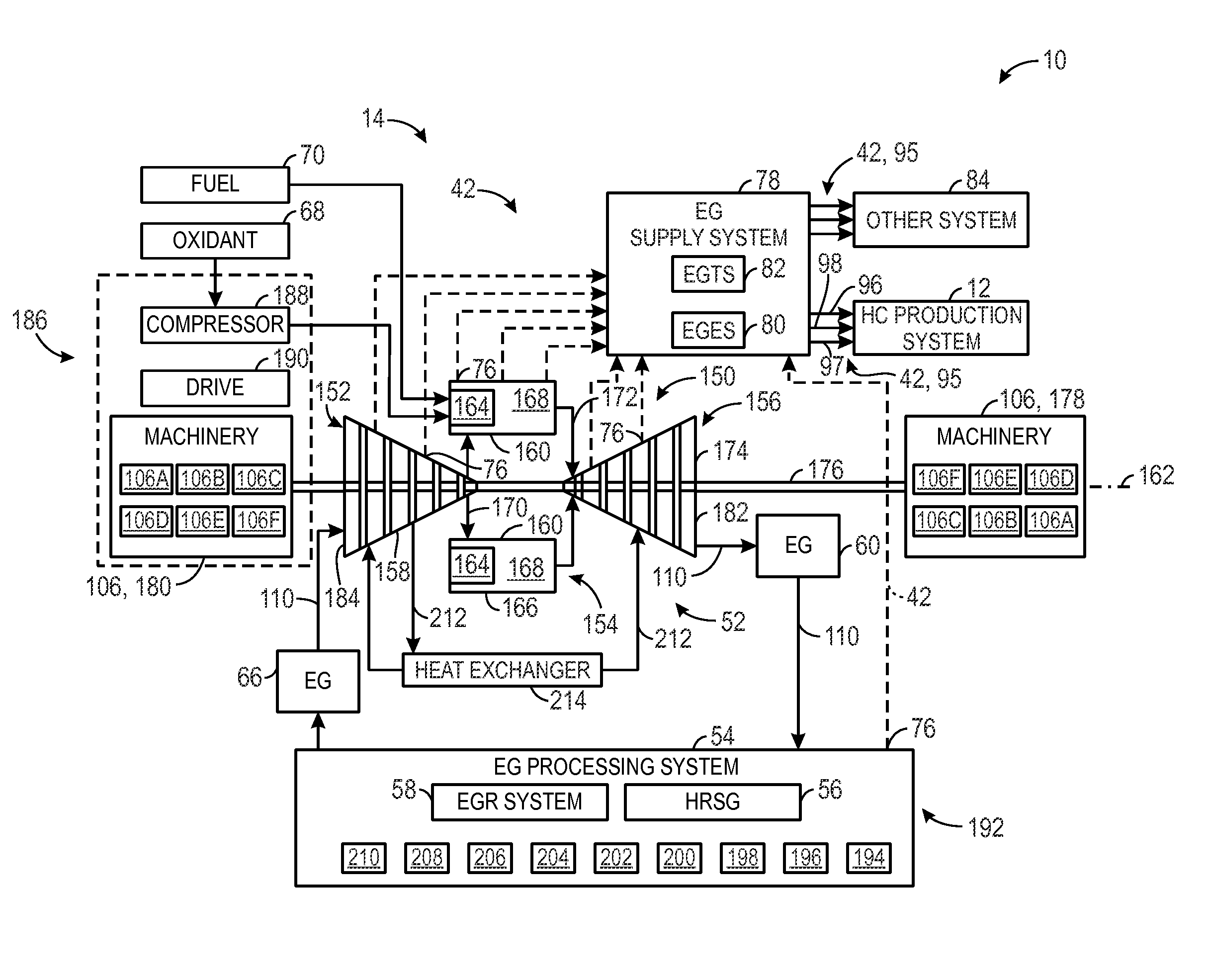
[0089] A system, comprising: a gas turbine engine configured to combust an oxidant and a fuel to generate an exhaust gas; a catalyst bed configured to treat the exhaust gas from the gas turbine engine to generate a treated exhaust gas; a differential temperature monitor configured to monitor a differential temperature between an inlet temperature of the exhaust gas and an outlet temperature of the treated exhaust gas; and an oxidant-to-fuel ratio system configured to adjust at least one of an oxidant flow rate of the oxidant, or a fuel flow rate of the fuel, or any combination thereof, based at least in part on the differential temperature.

[0090]Embodiment 2. The system of embodiment 1, wherein the oxidant-to-fuel ratio system comprises an oxidant compressor configured to adjust the oxidant flow rate.

embodiment 3

[0091] The system defined in any preceding embodiment, wherein the oxidant-to-fuel ratio system comprises an inlet guide vane of the oxidant compressor configured to adjust the oxidant flow rate.

embodiment 4

[0092] The system defined in any preceding embodiment, wherein the oxidant-to-fuel ratio system comprises a fuel control valve configured to adjust the fuel flow rate.


PUM


Abstract

A system includes a gas turbine engine configured to combust an oxidant and a fuel to generate an exhaust gas, a catalyst bed configured to treat a portion of the exhaust gas from the gas turbine engine to generate a treated exhaust gas, a differential temperature monitor configured to monitor a differential temperature between a first temperature of the portion of exhaust gas upstream of the catalyst bed and a second temperature of the treated exhaust gas downstream of the catalyst bed, and an oxidant-to-fuel ratio system configured to adjust a parameter to maintain an efficacy of the catalyst bed based at least in part on the differential temperature in order to maintain a target equivalence ratio.

Description

CROSS-REFERENCE TO RELATED APPLICATIONS[0001]This application claims priority to and benefit of U.S. Provisional Patent Application No. 61 / 911,912, entitled “SYSTEM AND METHOD FOR A GAS TURBINE ENGINE,” filed Dec. 4, 2013, which is hereby incorporated by reference in its entirety for all purposes.BACKGROUND[0002]The subject matter disclosed herein relates to gas turbine engines, and more specifically, to systems and methods for operating gas turbine engines.[0003]Gas turbine engines are used in a wide variety of applications, such as power generation, aircraft, and various machinery. Gas turbine engines generally combust a fuel with an oxidant (e.g., air) in a combustor section to generate hot combustion products, which then drive one or more turbine stages of a turbine section. In turn, the turbine section drives one or more compressor stages of a compressor section. Again, the fuel and oxidant mix in the combustor section, and then combust to produce the hot combustion products. U...

Claims


Application Information

Patent Timeline
IPC IPC(8): F01D25/30F02C3/34F02C6/00F02C9/28
CPCF01D25/30F02C9/28F02C3/34F05D2270/303F05D2220/32F05D2270/08F02C6/00F02C6/18Y02E20/16Y02T50/60F01D25/305
Inventor HUNTINGTON, RICHARD A.DHANUKA, SULABH K.
Owner GENERAL ELECTRIC CO
Why Eureka
Try Eureka