Engine exhaust gas purifier

a technology of exhaust gas and purifier, which is applied in the direction of liquid fuel feeder, machine/engine, electric control, etc., can solve the problems of significant advance of fuel ignition timing, long ignition delay, and inability to change ignition timing,

Inactive Publication Date: 2008-09-23
MAZDA MOTOR CORP
View PDF6 Cites 18 Cited by
  • Summary
  • Abstract
  • Description
  • Claims
  • Application Information

AI Technical Summary

Benefits of technology

[0006]The present invention has been made in view of the foregoing points and, therefore, its object is to provide a diesel engine that concurrently enables low emission and improved fuel economy.

Problems solved by technology

One of technical challenges for diesel combustion is to significantly reduce NOx and soot while maintaining good fuel economy.
According to the combustion system as described in the published document, however, a significant advance of the fuel ignition timing provides a very long ignition delay.
Therefore, even if the fuel injection timing is changed to some extent, the ignition timing cannot be changed.
Alternatively, if an attempt is made to control the ignition timing to near the top dead center on each compression stroke by increasing the amount of EGR to further extend the ignition delay time, this causes lack of oxygen to significantly increase HC and CO and thereby deteriorate the fuel economy.
As a result, the combustion system as described in the published document cannot control the ignition timing to an appropriate timing.

Method used


Image

  • Engine exhaust gas purifier
  • Engine exhaust gas purifier
  • Engine exhaust gas purifier

Examples


Embodiment Construction

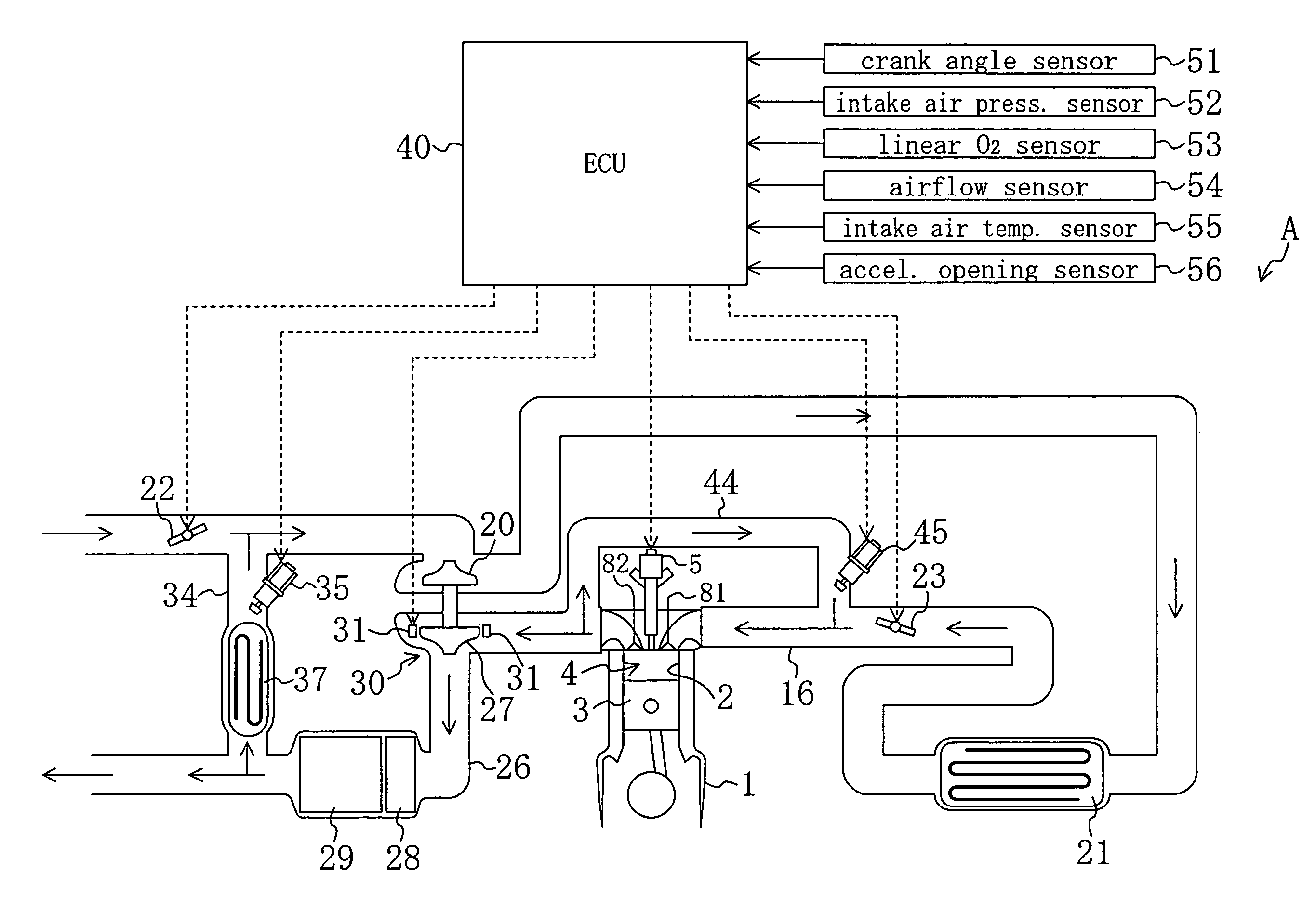
[0040]A description is given below of embodiments of the present invention with reference to the drawings. FIG. 1 shows an example of an engine exhaust gas purifier A according to an embodiment of the present invention. In the figure, reference numeral 1 denotes a diesel engine mounted on a vehicle. The engine 1 includes a plurality of cylinders 2, 2, . . . (only one is shown in the figure). Each cylinder 2 contains a piston 3 reciprocably fitted therein. The piston 3 defines a combustion chamber 4 in the associated cylinder 2. The combustion chamber 4 is provided at the top with an injector (fuel injection valve) 5. High-pressure fuel is injected from a nozzle at the tip of the injector 5 directly into the associated combustion chamber 4.

[0041]Although not shown in FIG. 1, the structure for supplying fuel to the injector 5 in each cylinder 2 is of the so-called common rail type that includes a common fuel distribution pipe (common rail) connected with all the injectors 5. The fuel ...


PUM


Abstract

An engine exhaust gas purifier includes: an injection controller allowing a fuel injection valve to inject fuel near the top dead center on each compression stroke; an EGR amount controller for controlling the amount of exhaust gas recirculated into a combustion chamber; an excess air ratio controller for controlling the excess air ratio so that the local equivalence ratio in a late combustion stage is lower than the equivalence ratio at which soot is produced; and an intake air temperature controller for controlling the temperature of intake air after being mixed with exhaust gas. The intake air temperature controller controls the temperature of intake air within a temperature range lower than an upper temperature limit below which a predetermined ignition delay time can be secured and higher than a lower temperature limit above which the production of HC and CO can be avoided.

Description

BACKGROUND OF THE INVENTION[0001](a) Field of the Invention[0002]This invention relates to exhaust gas purifiers for diesel engines.[0003](b) Description of the Related Art[0004]One of technical challenges for diesel combustion is to significantly reduce NOx and soot while maintaining good fuel economy. There is a known diesel combustion system capable of significantly reducing both of NOx and soot by recirculating a large amount of exhaust gas by EGR to reduce the combustion temperature and by injecting fuel relatively early for well mixture with air and causing the premixture to autoignite at the end of every compression stroke (see, for example, Published Japanese Patent Application No. 2001-82233).[0005]On the other hand, an ideal combustion condition from the aspect of fuel economy is to accurately control the ignition timing to near the top dead center on each compression stroke in order to minimize the total sum of time loss, cooling loss and mechanical loss. According to the...

Claims


Application Information

Patent Timeline
Patent Type & Authority Patents(United States)
IPC IPC(8): F02M25/07
CPCF02D41/005F02D41/403F02M25/0707F02M25/0709F02B29/0406Y02T10/47F02M25/0718F02M25/0727F02M25/0744Y02T10/44F02M26/05F02M26/06F02M26/15F02M26/23F02M26/38Y02T10/40
Inventor SHIMO, DAISUKEKATAOKA, MOTOSHIFUJIMOTO, MASAHIKOFUKUDA, DAISUKE
Owner MAZDA MOTOR CORP
Why Eureka
Try Eureka