Eureka AIR delivers breakthrough ideas for toughest innovation challenges, trusted by R&D personnel around the world.

Biomass gasification method

A biomass and gasification agent technology, applied in the field of biomass gasification, can solve the problems of difficulty in realization, low carbon conversion rate in the system, and high tar content, and achieves the improvement of biomass conversion utilization rate, prolongation of residence time, and easy operation. Effect

Active Publication Date: 2010-08-18
山东山科环境资源有限公司
View PDF2 Cites 19 Cited by
  • Summary
  • Abstract
  • Description
  • Claims
  • Application Information

AI Technical Summary

Problems solved by technology

However, the pyrolysis process of the technical solution disclosed in this patent requires an external heat source, and the entire method requires multiple equipments, and the system structure is complex. In addition, the semi-coke above the grate and the gas descending after reduction still have a high Carbon content, the carbon conversion rate of the system is low
[0004] From the above content, it can be seen that the traditional gasification technology has the disadvantage of high tar content, and the existing gasification technology has the disadvantages of requiring an external heat source for the pyrolysis process, difficulty in realization, and complex structure of the system device.

Method used


Image

  • Biomass gasification method
  • Biomass gasification method
  • Biomass gasification method

Examples


Embodiment 1

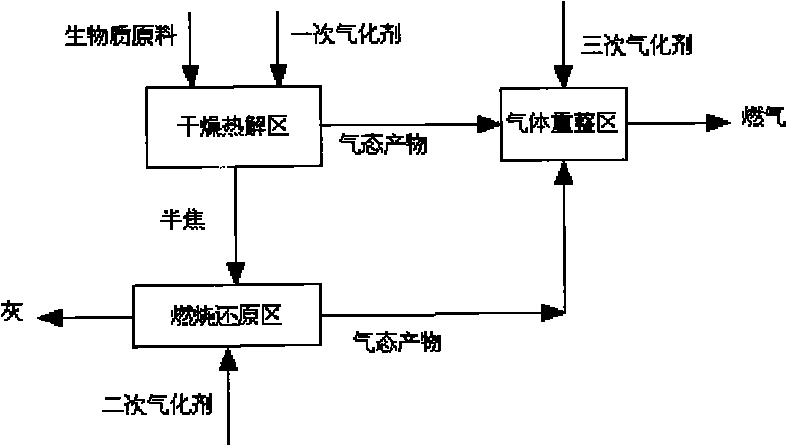
[0039] Such as figure 1 As shown, the three steps of dry pyrolysis, combustion reduction and gas reforming experienced by biomass gasification are relatively separated and carried out step by step. Biomass raw material and primary gasification agent undergo dry pyrolysis and partial gasification reaction under the condition of indirect heating, and semi-coke after pyrolysis and partial gasification undergoes combustion and reduction with secondary gasification agent introduced in the combustion reduction zone The gaseous products after reaction, pyrolysis and partial gasification and the gaseous products produced by combustion reduction are mixed in the gas reforming zone, and then undergo incomplete combustion reaction with the tertiary gasification agent passed in, forming a high temperature zone above 1000 ° C, and realizing tar High temperature enhanced cracking and reforming process of product gas, and finally high-quality product gas with almost no tar is obtained.

Embodiment 2

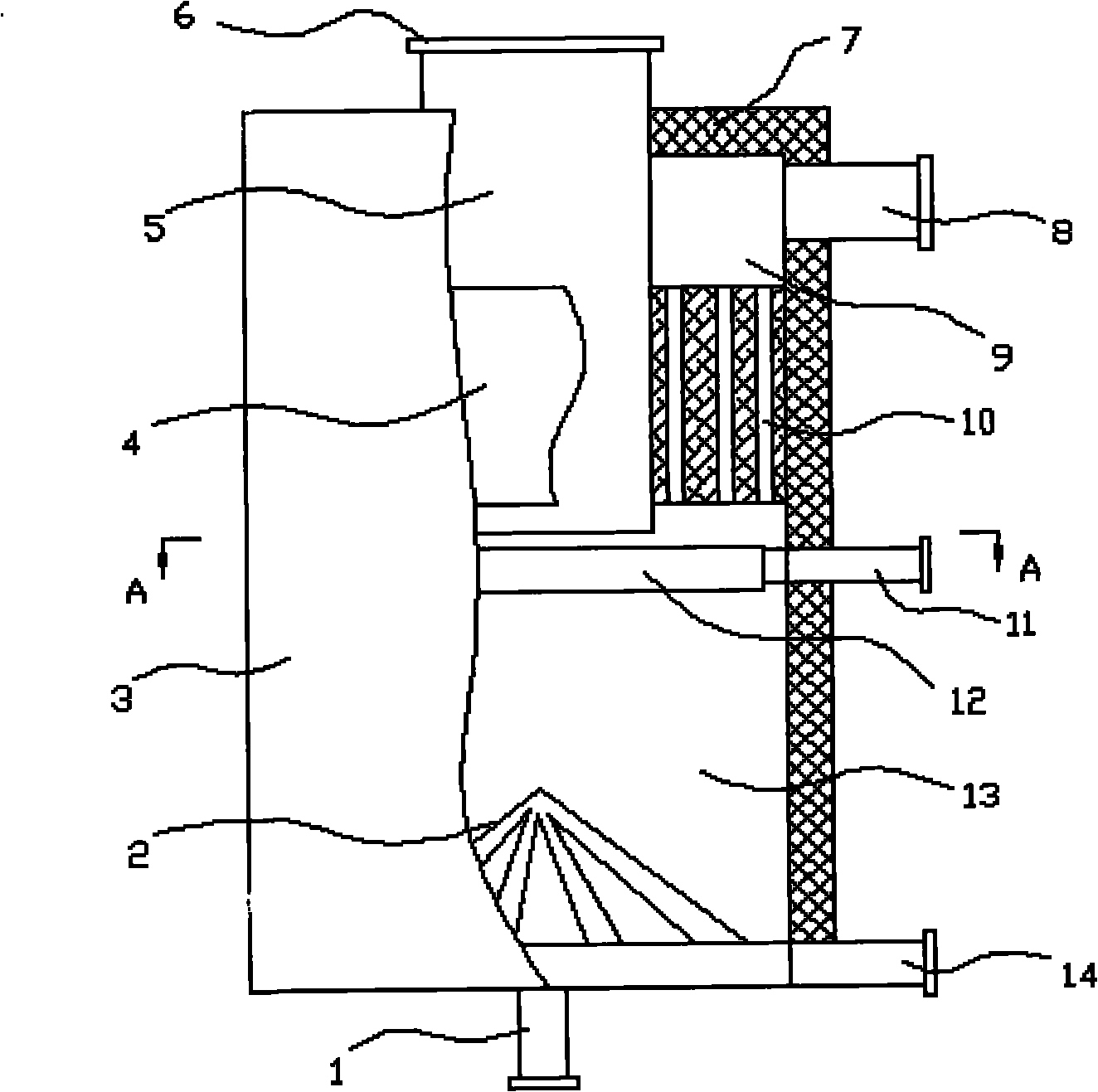
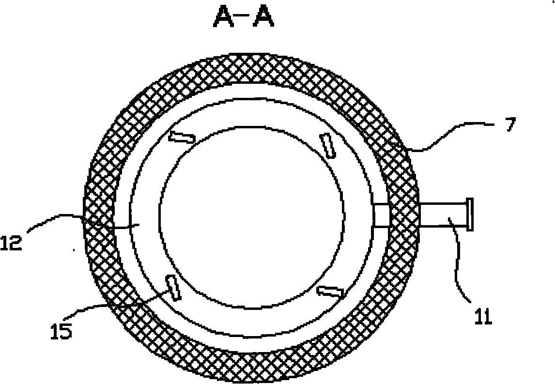
[0041] Such as figure 2 As shown, the biomass gasification furnace of this program includes a furnace body 3 with an insulating layer 7, a raw material inlet 6, a product gas outlet 8 and a gasification agent inlet are arranged on the furnace body 3, and a fire grate 2 is arranged at the bottom of the furnace body 3 And ash outlet 13, this scheme is to have the pyrolysis tube 5 of steel cylindrical cylinder coaxially with furnace body 3 on described furnace body 3, the upper opening end of this pyrolysis tube 5 is raw material inlet 6, and height Out of the upper top of the furnace body 3 , the lower open end of the pyrolysis cylinder 5 is located in the middle of the furnace body 3 . There is an annular gas reformer 4 between the periphery of the pyrolysis cylinder 5 and the inner wall of the furnace body 3. The position of the gas reformer 4 is in the middle and lower part of the pyrolysis cylinder 5. The gas reformer 4 It is made of high-temperature-resistant materials, an...

Embodiment 3

[0046] Such as figure 2 As shown, in the absence of a primary gasification agent, only the biomass raw material is fed into the pyrolysis cylinder (5) through the raw material inlet and the primary gasification agent inlet (6), and passed through the gas reformer (4) at a temperature above 1000°C The high-temperature gas is heated, and dry pyrolysis occurs; the pyrolyzed solid product semi-coke enters the combustion chamber (13), falls on the grate (2), and is combined with the gasification gas entering from the secondary gasification agent inlet (1). The combustion and reduction reaction of the agent occurs, and the solid residue after the reaction is discharged from the furnace body through the ash outlet (14); the gaseous matter produced by pyrolysis in the pyrolysis cylinder (5) and the semi-coke in the combustion chamber (13) are The gaseous substances produced by combustion and reduction are mixed with the gasification agent ejected from the gasification agent inlet (11)...


PUM


Abstract

The invention discloses a biomass gasification method. The method requires the steps of drying pyrolysis, combustion deoxidization and gas reforming in the gasification process to be relatively separated and continuously carried out in the same gasification furnace, simultaneously continuously gasification agent is introduced at three points in the whole gasification process and finally the cleanhigh quality product gas is obtained. In the invention, the equivalence ratio of the total gasification agent is 0.2-0.35, and the mass ratio of a first gasification agent, a second gasification agent and a third gasification agent is (0-0.8):(2-3.5):(0.7-1.5). The method controls the temperature and the reaction depth of each subarea in the furnace by controlling the mutual ratio of the biomass materials, the first gasification agent, the second gasification agent and the third gasification agent so as to control the quality of the final product gas. The obtained product gas can be used as the energy or the chemical engineering synthesis raw material gas. The method can generate clean product gas from the biomass, cannot generate secondary pollution and has high carbon conversion rate and simple implementation method.

Description

technical field [0001] The invention belongs to the technical field of biomass energy conversion, in particular to a biomass gasification method Background technique [0002] With the increasingly tense energy supply situation and the increasing awareness of environmental protection, renewable and almost pollution-free biomass energy has attracted more and more attention. Gasification is one of the important ways to utilize biomass energy. Biomass gasification is a process in which biomass is used as raw material, air, oxygen (or oxygen-enriched gas), water vapor, etc. are used as gasification agents, and biomass is converted into combustible gas through thermochemical reaction under high temperature conditions. The goal of gasification is to transfer the energy in the raw material to the combustible gas as much as possible, while minimizing the tar content in the gas. [0003] Whether it is a fixed bed or a fluidized bed, there is a lot of tar in the gas produced by the t...

Claims


Application Information

Patent Timeline
IPC IPC(8): C10J3/66C10J3/64C10J3/20C10J3/84
Inventor 许敏孙荣峰闫桂焕孙立关海滨张卫杰姜建国李晓霞
Owner 山东山科环境资源有限公司
Why Eureka
Eureka Blog
Learn More