
Fluid Actuated Over-Center Clutch for a PTO

a technology of hydraulic/pneumatic clutch and over-center clutch, which is applied in the direction of fluid-actuated clutches, non-mechanical actuated clutches, clutches, etc., can solve the problems of reducing system efficiency, introducing new problems, and large portion of the entire clutch actuation assembly to be replaced with a costly substitu

Active Publication Date: 2015-10-29
TWIN DISC
View PDF4 Cites 6 Cited by
  • Summary
  • Abstract
  • Description
  • Claims
  • Application Information

AI Technical Summary

Benefits of technology

The present invention is a hydraulically or pneumatically actuated, over-center clutch that can be retrofitted onto a power take off unit of an engine or tractor. The clutch includes a cylinder assembly with a movable piston connected to a sliding sleeve, which is selectively actuated in opposite directions for engagement and disengagement. The clutch is selectively actuated during the engagement and disengagement periods, and pressure is only applied to the cylinder during these periods. The clutch can be retrofitted onto existing mechanical linkages or hydraulic systems, and it allows for easy replacement of the pre-existing clutch without the need for constant pressure application. The technical effects of the invention include improved engagement and disengagement control, reduced wear and tear, and improved durability and reliability of the power take off unit.

Problems solved by technology

These devices require a large portion of the entire clutch actuation assembly to be replaced with a costly substitute.
Such systems must maintain the applied pressure in order to keep the clutch engaged which generates heat and wear on multiple components, thus, reducing system efficiency.
While this addressed one problem, it introduced new problems.
This introduces a significant cost and also a complicated retrofit procedure.
The constant hydraulic force present increases the wear of the hydraulic parts as the forces are present for the whole duration of work required by the application.

Method used


Image

  • Fluid Actuated Over-Center Clutch for a PTO
  • Fluid Actuated Over-Center Clutch for a PTO
  • Fluid Actuated Over-Center Clutch for a PTO

Examples


Embodiment Construction

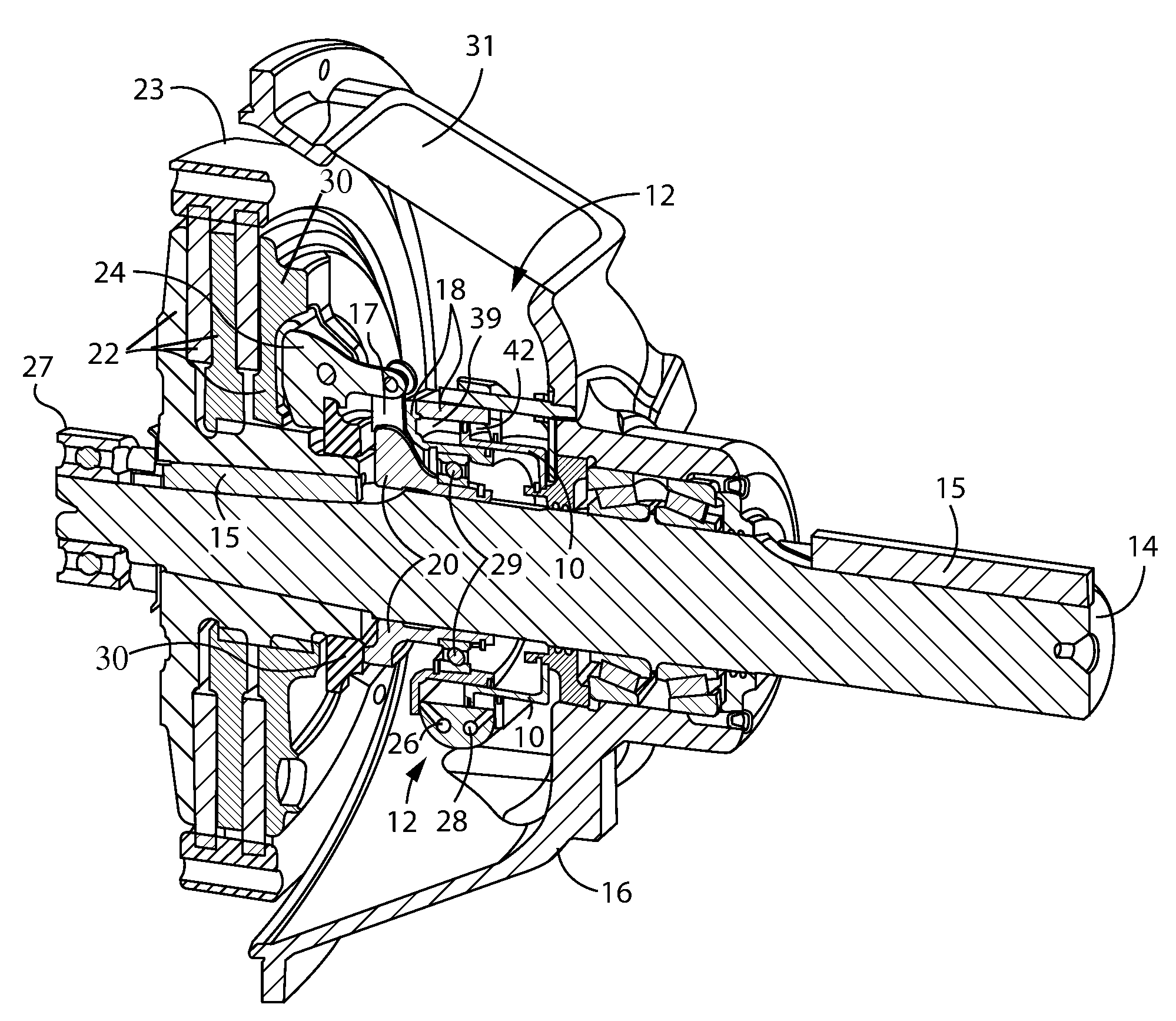
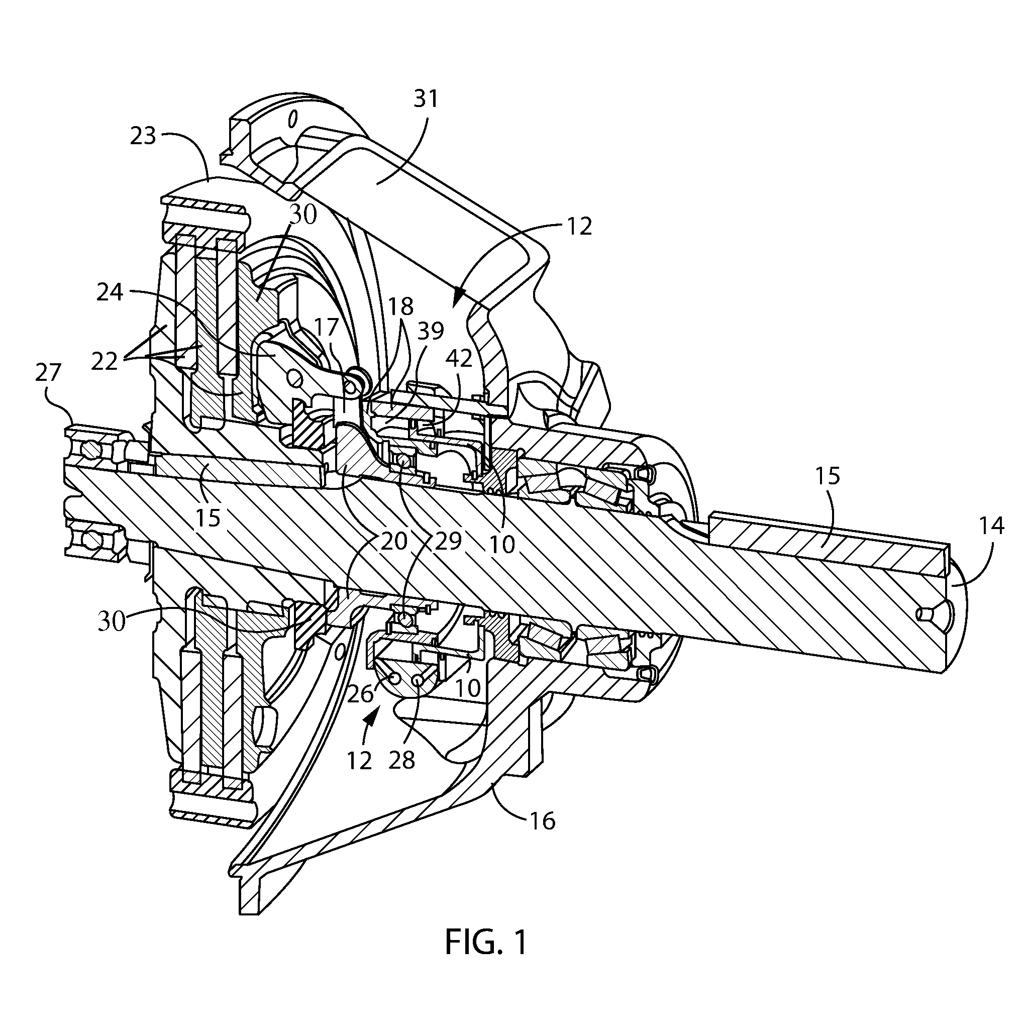
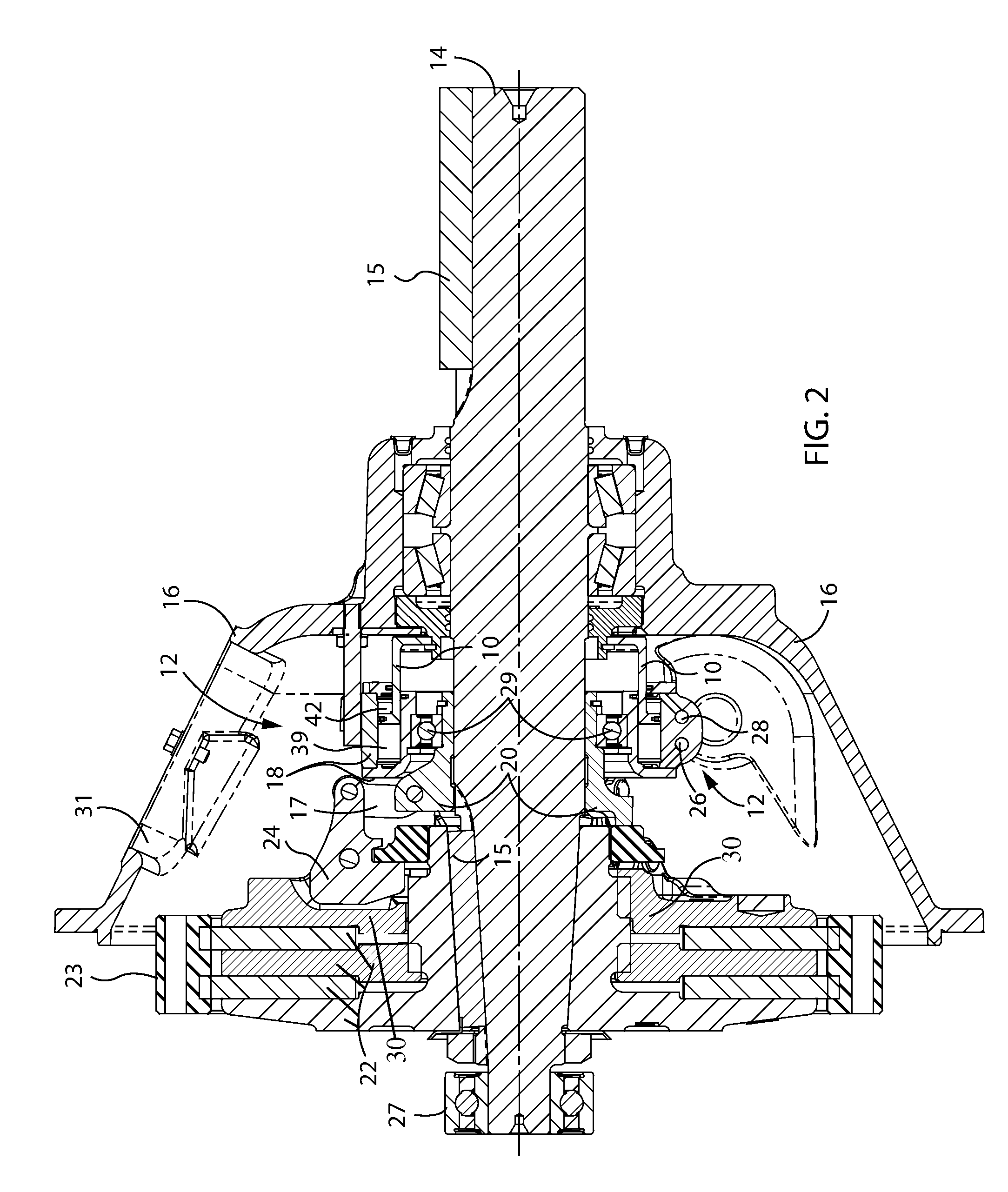
[0036]The preferred embodiments consist of a compact design for a hydraulic retrofit for clutch actuation in a PTO unit. The hydraulic retrofit is designed to fit within the PTO's bell housing and replaces the manual lever actuation, fulcrum, and fork of the mechanical clutch. The preferred embodiments further eliminates the need for a dedicated hydraulic circuit and cooling system to remotely engage the clutch by using the hydraulics of existing equipment utilizing the PTO. The retrofitted design utilizes approximately 90% of the existing mechanical (lever actuated) PTO. Using the existing mechanical linkage, costs are minimized, and the clutch may be kept in an engaged position without the need of constant application of pressure.

[0037]As a result, the preferred embodiments may be offered as a low cost retrofit to gain remote actuation of the clutch without compromising service life. The apparatus may easily be added to existing production PTOs as a remote control option. The appa...


PUM


Abstract

A hollow double-acting cylinder assembly may be mounted over a shaft and to a housing. A moveable piston of the cylinder assembly connects to a sliding sleeve of an over-center mechanism and the sliding sleeve with a thrust bearing allowing it to push and pull the sleeve mechanism with cylinder action. A toggle action of the over-center mechanism locks clutch without the need to sustain pressure on the cylinder after engagement / disengagement motion. As the clutch is typically engaged for sustained periods of time, this prevents constant hydraulic pressure applied to the over-center mechanism and significantly reduces wear. Hydraulic / pneumatic hoses may pass through the housing and connect to engage and disengage bores of the cylinder via remotely actuated control valve(s).

Description

CROSS REFERENCE TO RELATED APPLICATIONS[0001]This application claims a benefit of priority under 35 USC §119 to U.S. Provisional Patent Application No. 61 / 983,246 filed Apr. 23, 2014, the entire contents of which are hereby expressly incorporated by reference into the present application.BACKGROUND OF THE INVENTION[0002]1. Field of the Invention[0003]The present invention relates in general to the field of retrofitted hydraulic / pneumatic clutches and power take-offs “PTOs”. The terms hydraulic and pneumatic are used interchangeable and are intended to mean pressurized fluids in general, for example, pressurized hydraulic oil or compressed air.[0004]2. Discussion of the Related Art[0005]A power take-off or power takeoff (PTO) is any of several apparatus and methods for taking power from a power source, such as a running engine, and transmitting it to an application such as an attached implement, or separate machines. Most commonly, it is a system comprising a flywheel of an engine, w...

Claims


Application Information

Patent Timeline
IPC IPC(8): F16D25/08
CPCF16D25/083F16D25/087F16D13/385F16D23/12F16D48/02F16D2048/0212F16D2500/1026F16D2500/1028F16D2500/10437F16D2500/111
Inventor JONES, DARREL A.
Owner TWIN DISC
Learn More