Miniaturized imaging devices, systems and methods

Inactive Publication Date: 2015-10-29
INSCOPIX
View PDF0 Cites 25 Cited by
  • Summary
  • Abstract
  • Description
  • Claims
  • Application Information

AI Technical Summary

Benefits of technology

[0003]Recognized herein is the need for small, lightweight, c

Problems solved by technology

High performance imaging devices and systems remain bulky and expensive instruments.
These constraints increase with increasing imaging complexity, without the ability

Method used


Image

  • Miniaturized imaging devices, systems and methods
  • Miniaturized imaging devices, systems and methods
  • Miniaturized imaging devices, systems and methods

Examples


Embodiment Construction

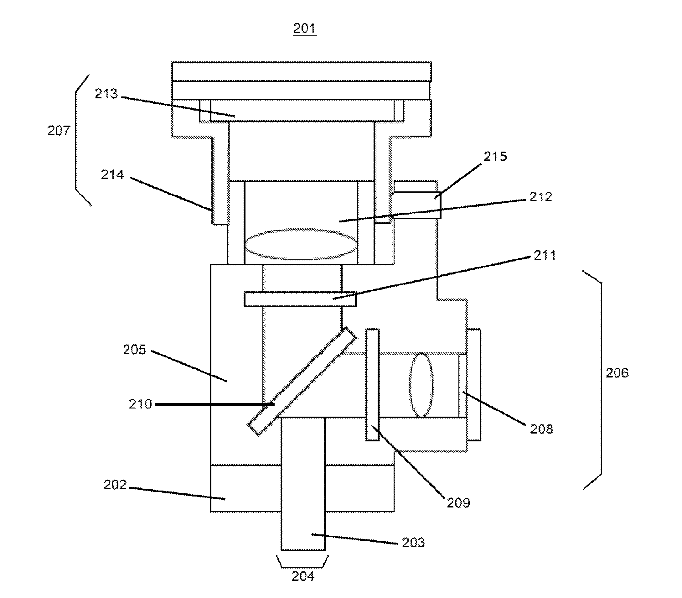
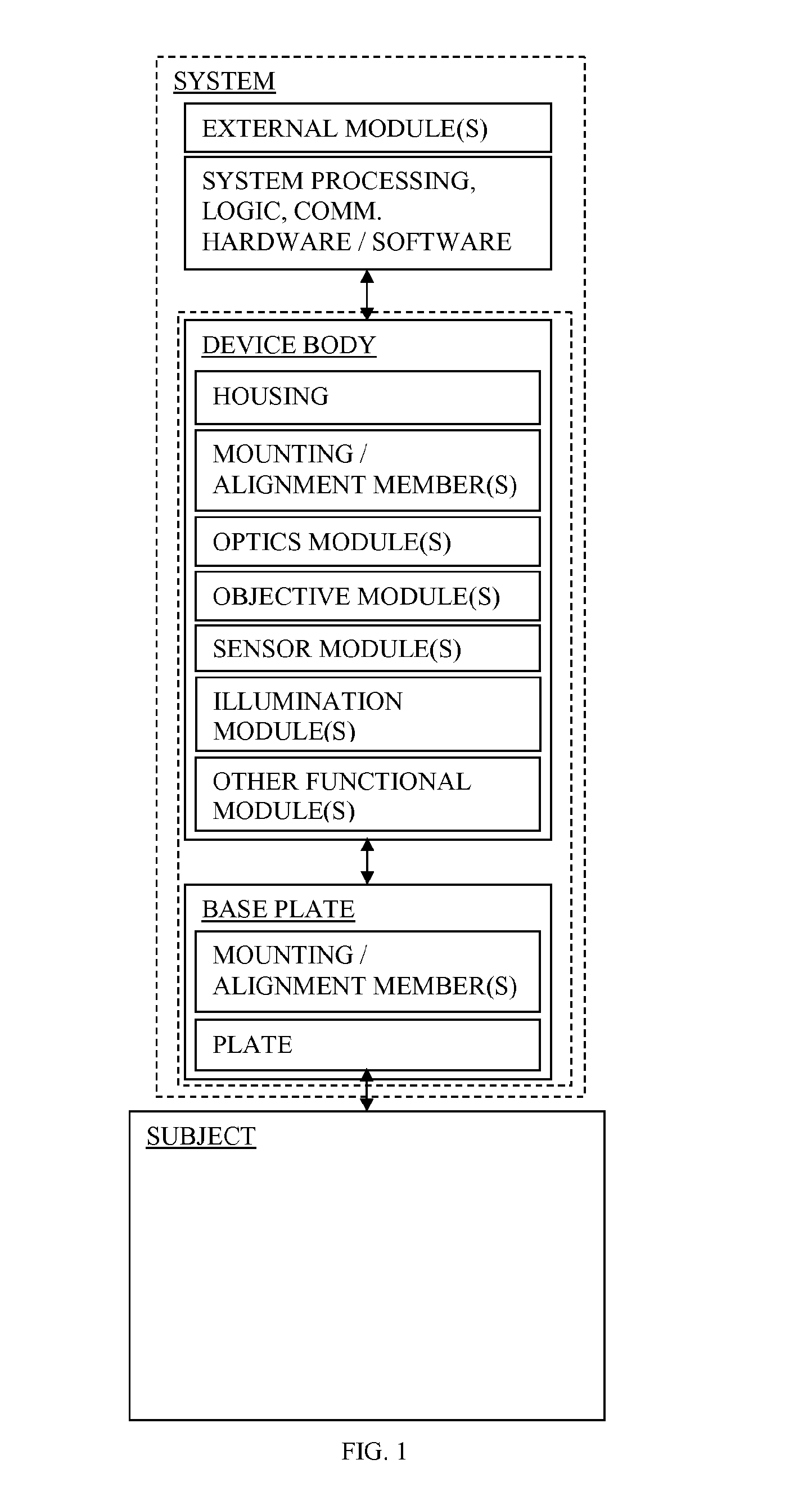
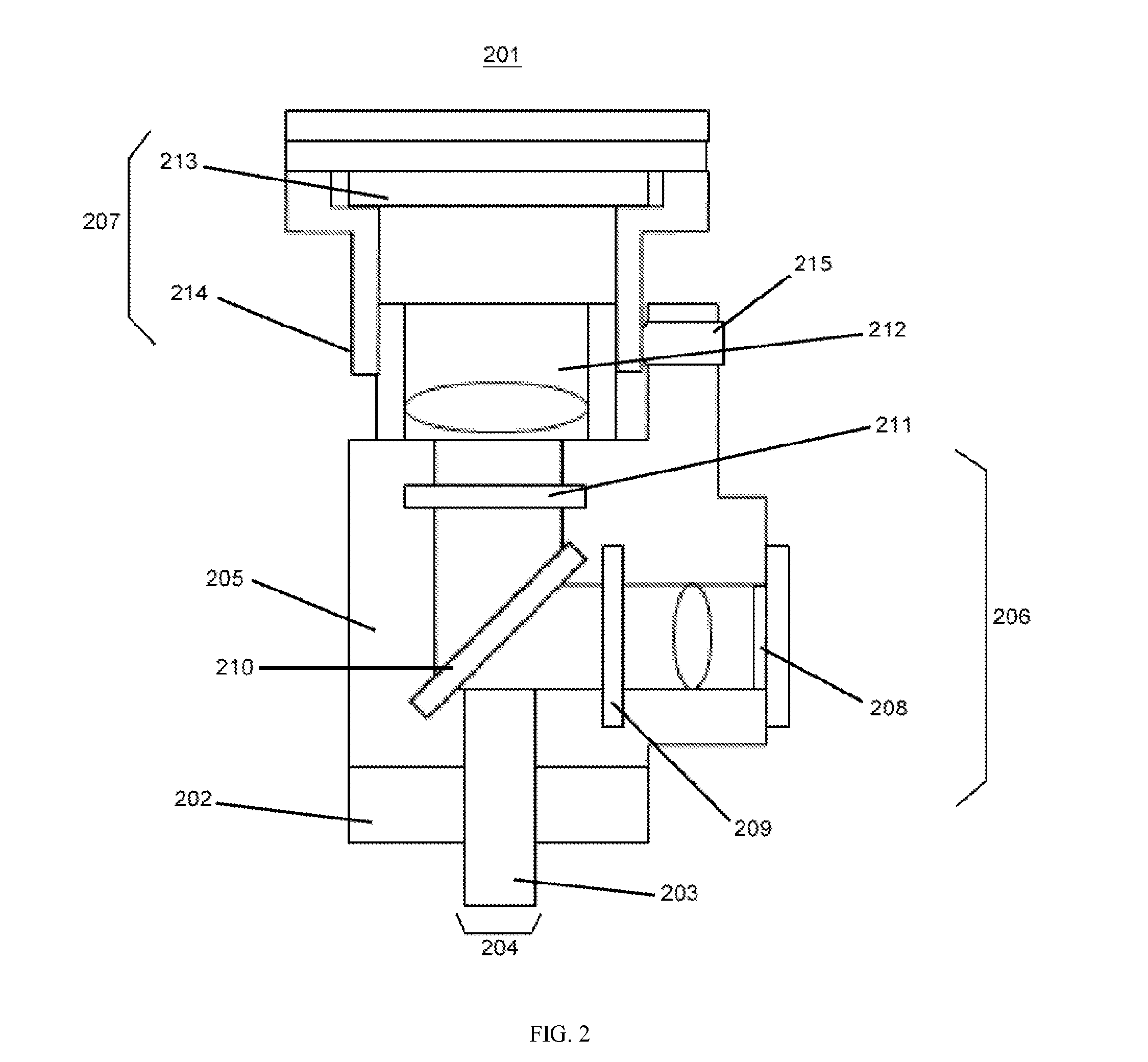
[0034]The invention provides miniaturized devices, systems and methods for imaging of biological specimens. In some embodiments, the invention provides devices, systems and methods for in vivo fluorescent brain imaging in freely-behaving rodents. Various aspects of the invention described herein may be applied to any of the particular applications set forth below or in any other type of imaging setting. The invention may be applied as a standalone method or system, or as part of an integrated imaging system. It shall be understood that different aspects of the invention can be appreciated individually, collectively, or in combination with each other.

[0035]Any description of alignment and assembly of optical and / or mechanical components for the purpose of miniaturized fluorescent imaging herein may also be applied to alignment and assembly of components (e.g., reflective or refractive optical surfaces such as lenses, mirrors, prisms or combinations thereof, wave guides or cavities, t...


PUM


Abstract

The invention provides miniaturized devices, systems and methods for imaging of biological specimens. The devices and system provide accurate alignment and modular mounting of imaging components internally and in relation to the target subject. In some embodiments, the invention provides devices, systems and methods for in vivo fluorescent brain imaging in freely-behaving rodents.

Description

CROSS-REFERENCE[0001]This application claims priority to U.S. Provisional Patent Application Ser. No. 61 / 722,721, filed on Nov. 5, 2012, which is entirely incorporated herein by reference.BACKGROUND OF INVENTION[0002]High performance imaging devices and systems remain bulky and expensive instruments. These constraints increase with increasing imaging complexity, without the ability to easily incorporate additional functionality. Present devices and systems are especially not well suited for distributed, chronic imaging of live biological specimens.SUMMARY OF INVENTION[0003]Recognized herein is the need for small, lightweight, customizable and easily assembled imaging devices and systems.[0004]The invention provides devices, systems and methods for miniaturized imaging of biological specimens. Some embodiments provide devices, systems and methods for miniaturized in vivo fluorescent brain imaging in freely-behaving rodents.[0005]An aspect of the invention relates to an imaging device...

Claims


Application Information

Patent Timeline
IPC IPC(8): G02B21/00G02B21/36G02B21/06A61B5/00
CPCG02B21/0076A61B5/0071G02B21/06G02B21/362A61B5/4064G03B17/02G03B15/00G03B17/561A61B5/0042
Inventor COCKER, ERICGHOSH, KUNAL
Owner INSCOPIX
Why Eureka
Try Eureka