
Measurement apparatus and method thereof

a measurement apparatus and three-dimensional technology, applied in the field can solve the problems of limiting the application range of three-dimensional measurement apparatus, affecting the accuracy of measurement, and taking a long time, and achieve the effect of fast measuremen

Inactive Publication Date: 2015-10-29
CANON KK
View PDF8 Cites 24 Cited by
  • Summary
  • Abstract
  • Description
  • Claims
  • Application Information

AI Technical Summary

Benefits of technology

The patent aims to quickly measure the shape of an object by using a pattern projection to remove the effects of internal scattering. This can be useful for measuring objects that are semi-transparent.

Problems solved by technology

Measurement by such an apparatus requires projection of many patterns and takes a long time.
For a target object made of a material such as plastic, the measurement accuracy may greatly degrade or measurement itself becomes impossible owing to a phenomenon called subsurface scattering or internal scattering.
This becomes an obstacle that greatly limits the application range of three-dimensional measurement apparatuses.
When a target object is formed from a material containing a semitransparent portion, high-accuracy measurement is difficult for the method disclosed in literature 1 such that no pattern can be recognized owing to internal scattering or the position of a pattern cannot be accurately specified from a captured image.
Although problems such as a decrease in accuracy caused by internal scattering and a measurement failure are solved, the number of projection patterns greatly increases, and a resultant increase in measurement time places a great constraint on practical use.

Method used


Image

  • Measurement apparatus and method thereof
  • Measurement apparatus and method thereof
  • Measurement apparatus and method thereof

Examples


first embodiment

[0030]A three-dimensional measurement apparatus described in an embodiment projects, to a measurement target object, structured light (to be referred to as “pattern light” hereinafter) having patterns in which the light and dark of a plurality of dashed lines are temporally changed. The respective dashed lines are discriminated in images obtained by capturing the series of projection images, and the influence of internal scattering generated in the measurement target object is removed, thereby quickly measuring the high-accuracy three-dimensional coordinates (three-dimensional shape) of the surface of the object.

[0031][Apparatus Arrangement]

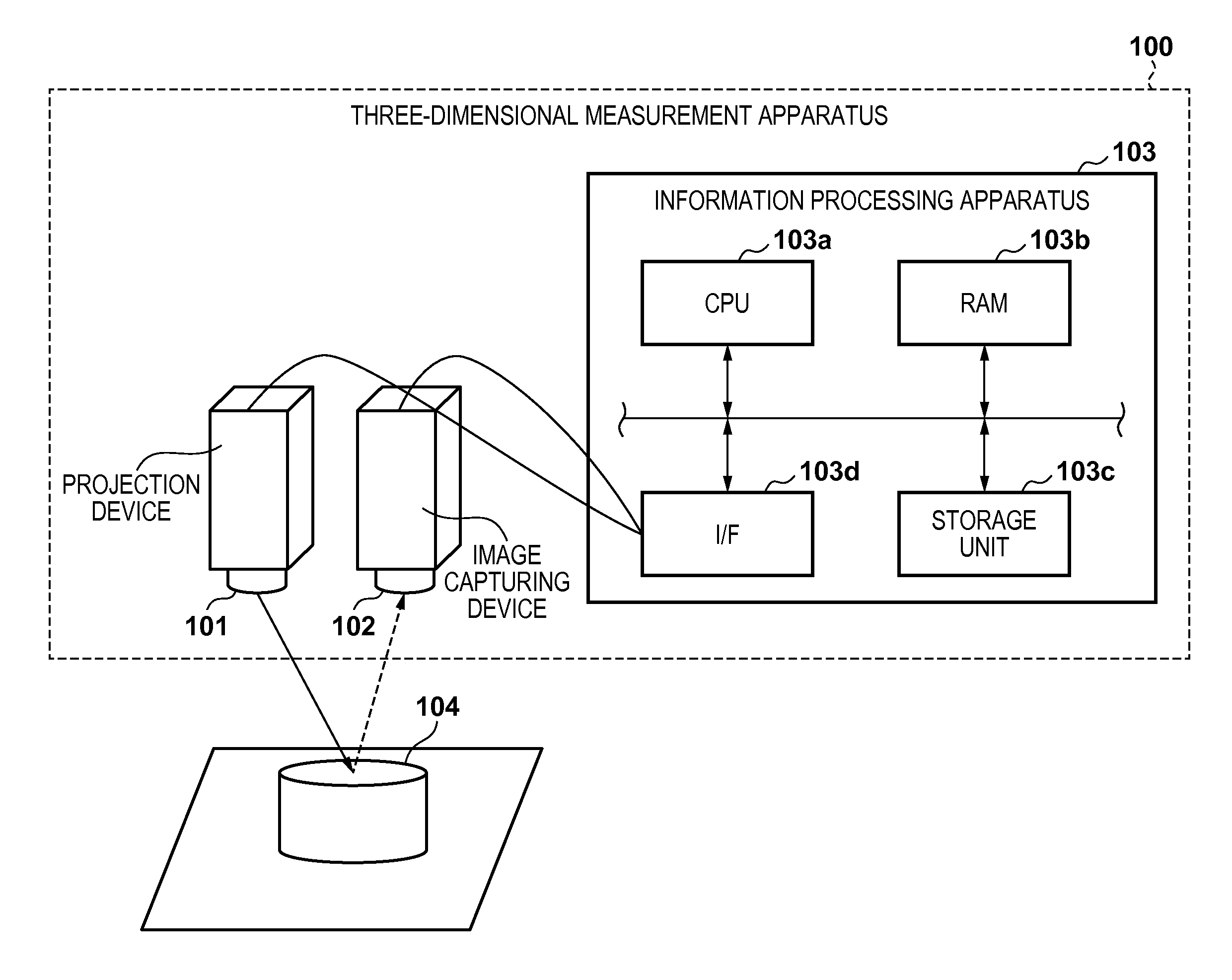
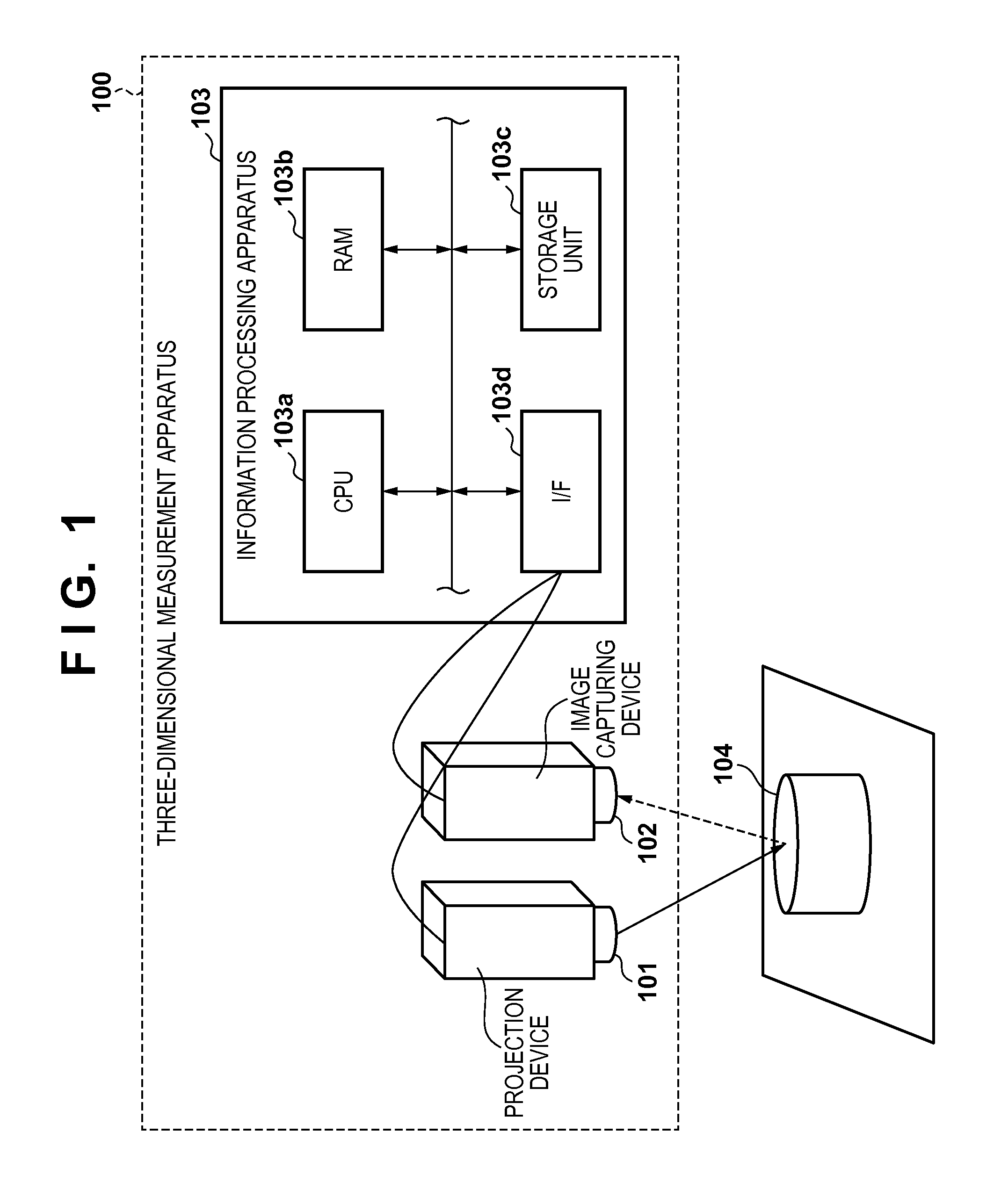
[0032]The arrangement of a three-dimensional measurement apparatus 100 according to the embodiment is shown in the block diagram of FIG. 1.

[0033]A projection device 101 projects pattern light (to be described later) to a measurement target object (to be referred to as a “target object” hereinafter) 104. The pattern light is reflected by the surfa...

second embodiment

[0075]Information processing according to the second embodiment of the present invention will be described below. In the second embodiment, the same reference numerals as those in the first embodiment denote the same parts, and a detailed description thereof will not be repeated.

[0076]In the second embodiment, a projection device 101 projects a space division pattern to divide a space including a target object 104 into a plurality of regions. Further, the projection device 101 projects, in the divided regions, coordinate detection patterns including a plurality of uniquely discriminable dashed lines. While removing the influence of internal scattering generated in the target object 104, the three-dimensional coordinates of the surface of the target object 104 are measured quickly at high accuracy. In the second embodiment, it is possible to project a larger number of dashed lines than those in the first embodiment and discriminate these dashed lines, implementing higher-speed measur...

third embodiment

[0091]Information processing according to the third embodiment of the present invention will be described below. In the third embodiment, the same reference numerals as those in the first and second embodiments denote the same parts, and a detailed description thereof will not be repeated.

[0092]In the third embodiment, a plurality of dashed lines are continuously projected to line regions in time series. The third embodiment will explain an example in which the respective line regions are discriminated (dashed lines are discriminated) in images obtained by capturing the projection images, and the influence of internal scattering generated in a measurement target is removed, thereby precisely measuring three-dimensional coordinates on the surface of the measurement target.

[0093][Apparatus Arrangement]

[0094]The function of an information processing apparatus 103 according to the third embodiment will be explained with reference to the block diagram of FIG. 10. The information processi...


PUM


Abstract

Images are obtained from an imaging device. The images represent patterns projected in a time series by a projection device. Each pattern comprises dashed lines each of which has a predetermined width. A longitudinal direction of each dashed line is substantially perpendicular to a base line defined by a segment connecting optical centers of the projection and imaging devices. Each dashed line repeats light and dark in the longitudinal direction. The dashed lines are discriminated based on combinations of the light and dark in the images. Correspondences between projected coordinates and image coordinates of the dashed lines are detected based on information regarding the patterns and a discrimination result of the dashed lines. A three-dimensional shape of the object is calculated based on the correspondences, and calibration data of the projection and imaging devices.

Description

BACKGROUND OF THE INVENTION[0001]1. Field of the Invention[0002]The present invention relates to measurement of the three-dimensional shape of a measurement target object.[0003]2. Description of the Related Art[0004]There is known a three-dimensional measurement apparatus that projects structured light to a measurement target object (to be referred to as a “target object” hereinafter) from a projection unit such as a projector, and obtains the three-dimensional coordinates of the target object by the principle of triangulation based on a position at which an image capturing unit has observed the reflected light. Measurement by such an apparatus requires projection of many patterns and takes a long time.[0005]As a method of shortening the measurement time, there is a method disclosed in Japanese Patent Application No. 63-103375 (literature 1). According to this method, a plurality of slit patterns divided into small segments are simultaneously projected to a target object. The corres...

Claims


Application Information

Patent Timeline
Patent Type & Authority Applications(United States)
IPC IPC(8): G06T17/20G01B11/25H04N9/31G06T7/00H04N13/02
CPCG06T17/20G06T7/0018G01B11/2513H04N9/31G01B11/2504H04N13/0275G06T2207/10016G06T7/521
Inventor YAMASAKI, MASAYOSHIKOBAYASHI, TOSHIHIROHIGO, TOMOAKI
Owner CANON KK
Features
  • Generate Ideas
  • Intellectual Property
  • Life Sciences
  • Materials
  • Tech Scout
  • Unparalleled Data Quality
  • Higher Quality Content
  • 60% Fewer Hallucinations
Learn More